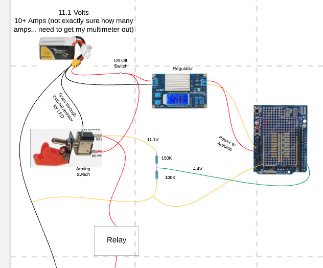
Model rocket launch controller. I've simplified my schematic.
I keep frying my board... How can I input the switch into the board while protecting it from the unregulated current?
Welcome to the forum.
This is not a schematic. Its a pretty picture.
A simple solution would be a switch with two isolated switches inside.
If that does not help you might need to provide some more information about the system. e.g., links to the datasheets of those non-Arduino boards and a schematic.
Yeah, I've looked for an illuminated double-pole switch—but I've come back empty handed. ![]()
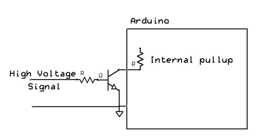
Use a resistor divider to bring down the high voltage to a safe level. Instant destruction is likely if the Arduino sees any voltage higher than Vcc+0.3V - your continuity test wire seems to do just that. At the very least have a 10k resistor or similar value in series with any wire that could have excess voltage - limiting the current to sub-milliamp levels should afford protection.
LiPo batteries can source 10's or 100's of amps, so you definitely need a fuse in that circuit
to protect from short-circuits burning up the wiring and starting a fire.
I also tried to put an IN4007 Diode between the switch and the pin and it still didn't help.
Please confirm the GND on the voltage regulator output is the same as the GND on the input of the voltage regulator.
What voltage do you measure on the digital input when the toggle switch is operated ?
Why not just use a digital input read (digitalRead()) to detect 5V on the switch contact that connects to the relay ? If the read returns "1" , then the switch is armed.
There is a lot more than 5v going through the switch. There is enough current that it overcomes the internal resistor and damages the board.
Full charged 3S Lipo is close to 12.6V.

I would simply put a 10K resistor in series with the wire to the Arduino. I will put 700µA through the protection diodes but cause no harm to the Arduino.
Folks will say this is not a technically elegant solution however the Microchip tech rep assures me it is a perfectly valid approach.