hi, i am using atmega328p, i want to measure duration of the pulse in INT0 pin.
i think that i can set INT0_vect for activating TIMER0_OVF_vect which is prescaled and calculated for overflow for every 1 microseconds. but it is not working the way i expected. what can i do?
i think problem is with INTF0
I am expecting from 14 to 75 microseconds duration
as i said, the pulse goes to INT0 pin (PIND2). when INT0 fired, ISR(INT0_vect) activates TIMER0 clock source by "TCCR0B |= (1 << CS01);" and it sets num to 0 , so timer0 is starting to count milliseconds from 0 by incrementing num variable in each overflow interrupt.
yes INT0 gets continious 500Hz pulses, the pulse length strarts from 14microseconds. i need to measure the length of this pulse and if it is longer than 14 microseconds the led have to blink faster. The other timers are about transmitting part and blinking part of LED. I just got that i should use CTC mode and PWM mode for other timers. But i still dont know how to measure the pulse length. I atmega328p set for 8Mhz internal oscillator.
Please, clarify: 1. 500 Hz pulse means 500 cycles/sec. Correct? 2. Pulse length means period of a cycle. Correct? Or it is length of On-period? 3. Period of the 500 Hz signal is 2000 us. Then what is this: 14 us? //Edit 4. Do you want measure the period using INT0 and Timer0? Is it a home work exercise or some part of a project?
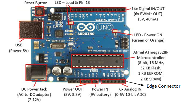
5. Do you have an Arduino UNO Board like below (Fig-1)? This Board can be operated at 8 MHz by programming the "System Clock Prescaler" in order to play with your codes of post #3.
Figure-1: