How to provide an easy to read schematic and how not

This tutorial shall show how to provide an easy to read schematic of your wiring and how you should

not

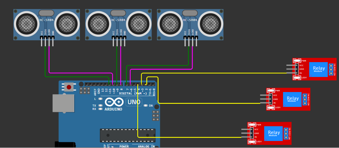
post fritzing pictures

don't post frizzy-pictures like that!

if you look at this pictures please tell me the IO-pin-numbers!
What ?? You can't read the IO-pin-numbers? You have to download the picture and than zoom in.
Don't you have time?
You have to download the datasheet of the chip and then look up which pin is connected to what.
take additional time to count through the chip-pins and carefully compare with the datasheet!

You give other users

extra work

for looking up datasheets to analyse what is connected to what.

that's how

careless amateurs

are doing it
.
.
a

hand-drawn

circuit diagram that follows the rules of

professional

circuit diagram drawing shows you are a carefully working hobby electronics engineer

This example is drawn extra-fast, extra-wiggly to demonstrate the important information is not in a straight line or a detailed picture. The important information is in giving only the important information.

By the way the above schematic is missing some wires that are nescessary to make it work

Here is a second example.
This picture looks fancy but is hard to analyse.
Too low resolution too many wires jumping around.

Well this is a somehow better attempt.
higher resolution which wire goes from where to where is easier to see.

Still this picture can't compete with this one for the following reasons:

  • all relevant information is there
  • all ir-relevant information is left out
  • much clearer wiring very easiy to follow what is connected to what.

It is the opposite of fancy. But is is very efficient. Quick to draw. Very quick to analyse.

And this is what makes a schematic professional.
best regards Stefan

7 Likes

That’s too bad for an example :slight_smile:

I’d say battery type and voltage is important
How is the arduino powered too
Resistors need their value
A little half circle to show cables are not connected but goes over one another helps, small dots are not always easy to spot
Components exact specification (which motor, which driver ?) are needed

1 Like

at least write in detail what you think should be improved or provide a better one

1 Like

Sorry was editing as you replied to provide ideas - see above

Good post though - the intent is right

You do something that is worth noting…

Positive rails tend to the top of the diagram, and ground, then -Negative rails are placed further toward the bottom.

Signal flows LEFT TO RIGHT, not zig-zag wherever !

This inputs are coming from the left, heading toward outputs in the right.

I notice you avoided crossing over lines when not necessary - makes the drawing easier to follow.

A good start.

1 Like

Your frustration is palpable...
Similar to my motivation for creating the forum instructions, well done :smiley:

1 Like

Hi,
Asking an OP to draw a proper schematic by reverse engineering his/her project sometimes shows them the cause of the fault(s) they are asking assistance for.

What surprises me at the moment is the number of University/Bachelor final projects that are presented as Fritzy pictures to the forum.

By the time you are in final year you should have been taught how to draw a schematic, and use a proper engineering CAD program.

They should have been taught or provided resources of their educational institution to research and present their projects somewhat professionally.

Tom..... :frowning_face: :+1: :coffee: :australia:

2 Likes

That doesn't follow at all. The starting point of Arduino was, after all, to help those whose main line of study is not electronics or programming, but art for example. Or like me, pure science. My partner used Arduino and some sensors to capture the number of shoppers who turned this way or that when the displays were changed in a supermarket- that was for her psych masters let alone final year undergrad, she's not an engineer. She (as the song goes) got by with a little help from her friends (yes she acknowledged that assistance and advice in her work), and cobbled some stuff together. Learning Arduino was never her aim: it's a tool; the purpose of her work was to assess the impact of various displays in the shop, not to learn a cad system. She could just have easily have paid some undergrads to count traffic with hand-held counters, but had to be less obtrusive, hence Arduino. It was a better tool than using humans and she learned what she learned out of necessity, keeping that to the bare minimum. She doesn't know Computer Aided Doodling from Control-Alt-Delete.

4 Likes

That's not the point of @StefanL38's post

if your partner had to come here with a question and explain what s/he was doing, a diagram would have been appropriate.

The ask is to prefer a hand drawn circuit with enough readable information rather than a photorealistic image of what the composant look like but where you can't see what matters.

Agreed: but it was the point of @TomGeorge's that a final year B degree student using Arduino "should have been taught how to draw a schematic, and use a proper engineering CAD program."

1 Like

@hannah_mackinlay Yes I remember that. Arduino started with the aim to make it easier to use microcontrollers. Making it possible for artists etc. It has become easier but not as easy as installing an app on a smartphone or plugging in an USB-device into an USB-port.

For me this arises the question if there should be something like
"artist is searching for technical assistance for a non-profit art project"
Where it is cleary stated right from the start the artist wants to concentrate on the art-aspects
and needs technical assistance for software-developping.

Which is just the same thing as an electronic hobbiest isn't gonna build up is own little semiconductor-production. This comparison does not fit in all details. You buy electronic components. Of course you can buy software-development. But this is the problem for non-commercial projects. So maybe this is a suggestion for a new category non-profit projects.
Initiator of the project has to describe in detail the wanted functionality to find somebody why finds it interesting to give the technical assistance for software-developping in this porject.

The detailed description of the complete porject and the detailed description of the wanted functionality will keep out the persons that are too lazy to code for their assigment themselves.

best regards Stefan

I think this forum has more than enough categories to be honest.

My issue was with @TomGeorge insisting (or ok, suggesting?) that a final year B student should know CAD and that's not true imo. That's not to say that as @J-M-L said (quote below) if anyone comes here to get help they should be able to draw a schematic and that's absolutely true: your quick tutorial will surely help with that. (She did need to put a diagram in the M work I mentioned, as part of the explanation of the test set up, but a block diagram was enough, an good ol' PowerPoint's good for that.)

fair indeed. agree it's not always the case.

Hi @StefanL38 You're showing some bits of good advice, however there are a couple of issues.

1: You havent given a part number (or a link) for the motor driver.

2: schematics generally dont show how current flows in grounds, and this can be a problem especially if (as here) there are analog signal, digital signal and control grounds that should be connected to the battery -ve at a star point.

Your "schematic" is a hybrid between a layout diagram and a standards compliant schematic.
So all the motor current flows through the tracks on the arduino board.

3: Does the motor driver generate 5V for the arduino? Or vice versa?

4: maybe add a title that says what the circuit does?

:+1: :+1: :+1:

When I began this hobby around 2 years ago, with no clue about anything electronics/programming related, Fritzing cartoons were about the only thing I could understand, and I wished it wasn't frowned upon in this forum.

But, I eventually came to realise the effort it would take for other people to read and understand that crap.

So, if you want to get a volunteer to review your schematic, free of charge, then you should at least be considerate to them and take a few days to learn how to make a real schematic, that is both clear and readable. Nuff said.

1 Like

I have recently started 'tinkering' with the arduino and become interested in programming and electronics (again) and am currently trying to design an energy recording instrument. I often use Fritzing both to draw schematics and to design veroboard prototypes and find it very easy and convenient. I also use Tinkercad to test my designs although the simulator is not always very accurate. This is a very good tutorial on Fritzing on youtube: CMPE370: Fritzing Schematics - YouTube
This is an example of a recent schematic that I created and I would appreciate your comments on the quality and if you consider it of high enough quality to post on this forum. Thank you.

schematic follows common rules. Maybe adding type-numbers to the triac, optocoupler and the mos-fets

Thanks for the feed-back. In mitigation, this is a work in progress and I have not decided on the actual final choice of components. But I appreciate the comment.

A schematic for review here should be as complete as possible. Where is the Arduino power coming from? If a power supply is used, voltage and current ratings, and if possible a make/model.
I will refrain from commenting about what the circuit does(correctness) so as not to derail the discussion about the schematic process.