Instead of constant DC, I want to make pulsed DC for electroplating, which creates a better deposit of copper, hence the desire to pulse the current being supplied by this power supply. 10 ms pulse on, 10 ms pulse off is the ideal frequency.
Possible solution:
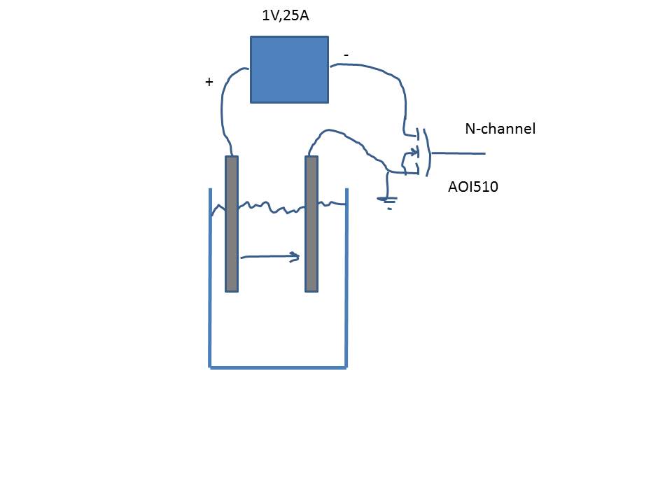
Program a PWM signal to switch on and off an optically-controlled mosfet. The Arduino is isolated from the high current this way. The mosfet is hooked up to the circuit that the power supply makes with the acid electrolyte plating bath. When the mosfet, which is wired to the positive lead coming from the DC side of the power supply, is switched on, it completes the circuit that the power supply makes with the plating bath; 1 volt of up to 25 amps is sent from the positive lead of the power supply, through the plating bath, and back up the negative lead in the power supply. This takes place for 10ms. Then the mosfet is switched off, the circuit is broken, and the bath is not powered for 10ms; this loops programmatically for several hours (electroforming, the building up of copper on the cathode into a somewhat thick shell, does take a bit of time).
This seems obvious, but I’ll point out that I’m not turning off and on the power supply itself, rather its output after it’s converted the AD to DC.
Questions:
Will this achieve my goal? If so, is there a better way to do it? Are there any essential components missing from the idea that would, without being in place, serve to ruin the power supply or create unnecessary danger (electroplating in acid with live wires is already dangerous enough)?
Thanks! That's the solution for which I was looking. I noticed that the transistor goes on the negative lead, and now understand that it is "common" practice to put it there instead of on the positive where I had envisioned it. I'm surprised that it will be this easy to accomplish the project goal. Next, I will consider ideas for throwing a negative pulse of higher current in to the mix, as even better than pulsed electroplating is reverse pulsed electroplating (occasional reverse pulses apply a little strategic electro-etching to even out the plating layers, removing tendrils and spikes from areas of highest current density on the cathode (item being plated)). It usually goes 20 pulses forward, 1 reverse at 2 to 3 times the current. I expect the solution will involve pumping a capacitor during the 10 ms off times, then driving that capacitor to make the reverse pulse. I'll make a drawing and better frame the question before moving forward with this next step. The drop in voltage as a capacitor discharges won't be a problem for plating.
If you want to reverse drive you'll need an H-bridge, perhaps for your
purposes a high current DPDT relay might be OK for the H-bridge
and you only use it to reverse the load...
Switching a capacitor will be even more complex potentially, and finding
one with a suitable capacity and ripple current rating would be challenging.
Hi platedbass. Would you mind sharing your chopper circuit with us, if at all possible? I have a very similar problem and it would really help if I don't have to reinvent the wheel.