Thanks.
I think it is the French translation that ends up using words that we would not use in English to describe things.
Thanks.
I think it is the French translation that ends up using words that we would not use in English to describe things.
Grumpy_Mike:
Thanks.I think it is the French translation that ends up using words that we would not use in English to describe things.
I see the item description is in English. Anyway, I copied the description below:
and this link has more details and photos.
http://www.ebay.com/itm/Bluebird-DAC3-0-CS4398-CS8416-SA9023-USB-DAC-descodificador-Amplificador-Para-Auriculares-/112053201337?_ul=GT&nma=true&si=VmIFKsY6%252BRduQRSPa6FFEOI2%252Fgo%253D&orig_cvip=true&rt=nc&_trksid=p2047675.l2557
For the same decoding chip, different filter circuit is one of the biggest influence. Bluebird uses its own independent development of filter circuit. Make sound more natural,clean,downy.
Specification:
Size: 22cm5cm12.5cm
Weight: 1.2Kg
Support the sampling rate:
Coaxial 24B 192K
Optical fiber 24B 192K
USB 24B 96K (XP,WIN7, WIN8. MAC driving free ,support mobile OTG decoding)
Decoding chip: CS4398+CS8416+SA9023
Headphone power: 460MW/32ohms
Input: USB/Coaxial/Optical or Analog input, Use back panel's switch button to switch betweenUSB/Coaxial/Optical input and Analog input
Output:
3.5jack headphone output on back panel, directly drived by decoder chip modul
6.5jack headphone output on front panel, drived by headphone amplification extend card
analog outputNotice :Look at picture of back part
Back panel left switcher is used to switch between USB/Coaxial/Optical input and Analog input
NC to reserve space. This interface without any function.
COA RCA socket for external coaxial input interface. Support maximum 24 b 192 k sampling rate digital signal input
OPT for external optical fiber input interface.Support maximum 24 b 192 k sampling rate digital signal input
USB to the computer USB port.Computer signal can be directly converted into a maximum 24 b 96 k input to decoding part.To optimize the output.
The decoder part's op-amps use three American big SNE5532 OPA. OPA adopts the plug type design you can freely change. Ascension decoder sound quality. Decoder op-amp adopts dual op-amp. So when you buy upgrade op-amp, pay attention to buy dual op-amp
Headphone amplifier card use two American SNE5534 single op-amp, It's not same with decoding part .You should pay attention to. The op-amp is still adopted plug type design.
The machine adopts full shield square transformer. Reduce interference. Improve signal-to-noise ratio.
Thank you Mike.
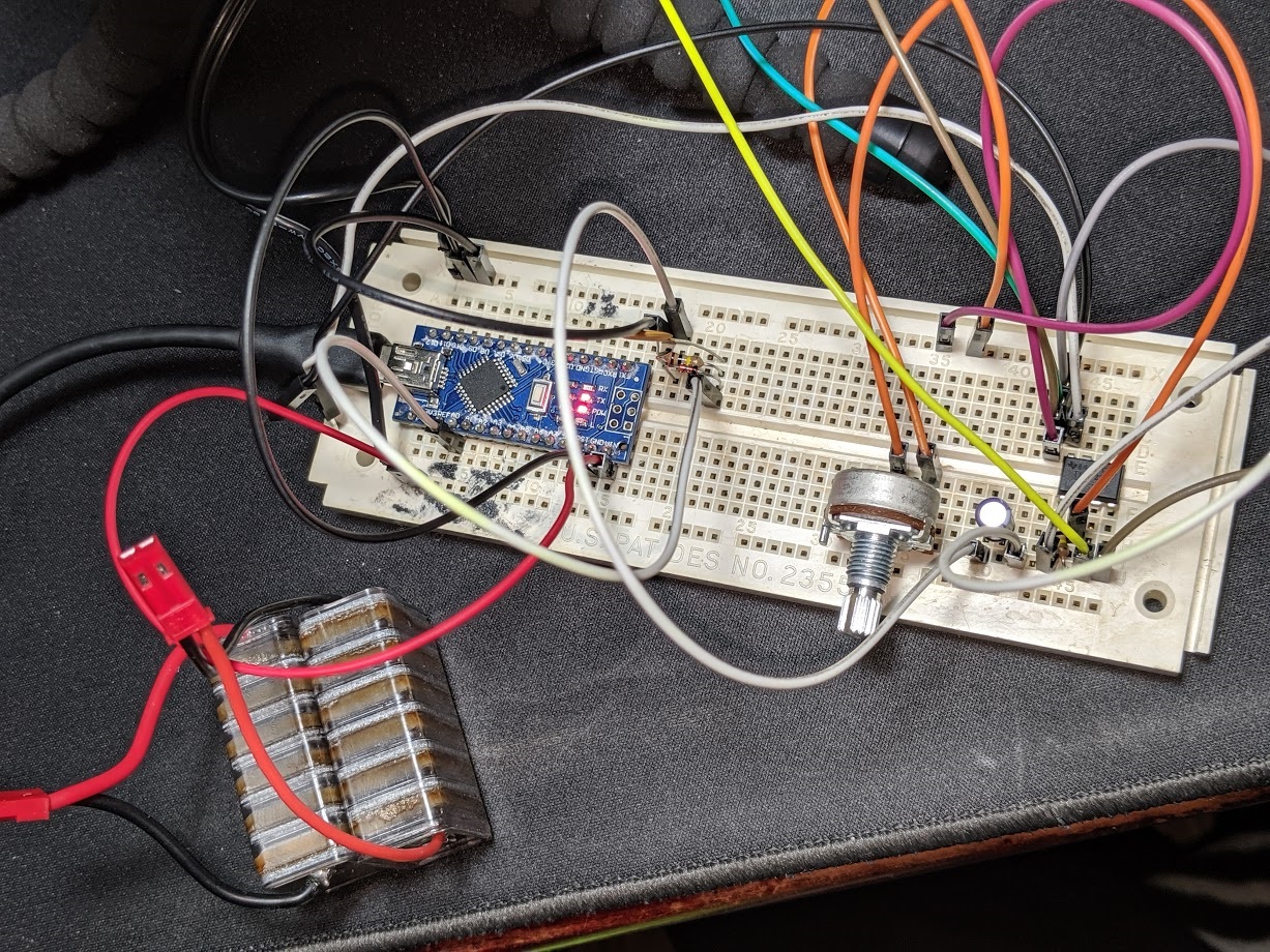
I have successfully built the circuit and the overall result looks good.
But the highest volume value is only about 220, when left and right channels send signal at the same time, the volume from the right channel is even lower.
Therefore, I use the left channel only for the best result now.
But the highest volume value is only about 220
That seems about right. If 1023 is 5V then 222 is about 1V. If there's a series diode, you're getting a ~0.6V drop across the diode so your audio signal is ~1.6V peak (3.2V peak-to-peak). That should be a fairly loud headphone signal.
You can try switching to the optional [u]1.1V internal reference[/u].
when left and right channels send signal at the same time, the volume from the right channel is even lower.
Of course the left & right channels should be approximately equal and you can check that with headphones.
Don't "short" the left & right channels together. That can potentially damage the DAC/headphone amp and it will probably "damage" the signal. If you need both channels you can build another identical circuit and use a 2nd Arduino analog input. Then if you don't need independent left/right signals you can sum the two channels in software.
Or, you can make a passive "mixer" with a couple more resistors to mix the left & right signals together through resistors.
But the highest volume value is only about 220,
So you need to either turn up the volume or make an amplifier.
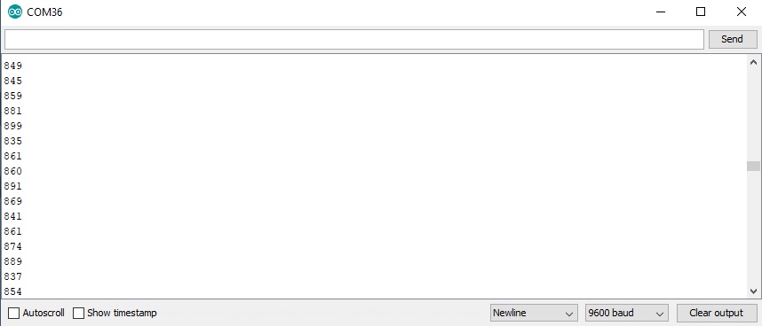
Okay so i built the described circuit and also added an op amp before it that allows me to control the gain of my inputting signal, I'm able to get the range from 0- 1023 which is awesome!, but when playing a constant 4000 Hz Test Tone from a YouTube video, within the serial monitor It's about +- 60 from where is is trying to hold the value, a constant sound should produce a constant number, how can I make this circuit more precise?
Please read the how to use this forum sticky post about posting images as attachments. We don’t like going off site here to places that force you to accept cookies. It also tells you not to hijack threads.
a constant sound should produce a constant number
No, what makes you think that? When you sample a sound you are sampling an instance in time. That could be anywhere on the waveform. The sound is being filtered but there will still be a bit of ripple on it, because you only have a first order filter anyway. There is a compromise between smoothness of reading and responsiveness of the circuit.
To get better results you would have to use a higher order of filter and look carefully at the roll off frequency.
Hello Grumpy_Mike, obviously you didn't see that I'm a Newbie, Yeah i figured that was going to happen with the images, I get it, and I was afraid that it was going to happen. It said to provide a URL so I did, I'll try harder next time. I'll see if I can fix it. and read up on what you are talking about
SORRY Mike but if you are implying that I'm am hijacking this thread you sir are wrong. dude really, and is not my intention to do that, my intention is to not only read data from a line level audio jack, but the data has to be good. I did build an amp like you suggested which is working great thank you. I'm continuing where you left off with kitce. I'm trying to get better data to work with so I can start to lean how to make them blink all fancy.
I know you could build this whole thing blindfolded but cut me some slack ggggg's
I'm new here.
I know you could build this whole thing blindfolded but cut me some slack ggggg's
Slack cut, but I was not cross with you in the first place, you will know when I am cross ![]()
If there is anything you didn't understand about what I said then please ask. The term "Newbie" can cover a whole variety of skill levels so if an answer is over your head then here we all encourage you to ask for an explanation about what you don't understand. The worst thing you can do is ignore what you don't understand.
In my opinion you would have been better to start your own thread because reading this on involves plowing through some dead ends before we get onto what the OP actually wanted. You can always post a link back to this one but I don't think that would be necessary, just the circuit you are using and the problem you are facing would have been enough.
I am trying to read the voltage of a 3.5 mm audio jack to detect if there is no audio on the input. I have created the above circuit as described earlier in the thread. I am not sure what code i should be using to read the voltage. I am using the ReadAnalogVoltage Arduino example program and i am not sure if that is right as i also am getting a consistent output of 0. Can anyone point me in the right direction it would be appreciated. I am new to this and a lot of the links posted on this thread are dead so i am a little lost.
jmjohnson419,
Your signal is probably too weak to overcome the diode's forward voltage drop.
What are you connected to? Can you turn-up the volume? (I hope you're not pugging-in a microphone... You only get a few millivolts from a microphone and electret computer microphones need to be powered.)
Try the bias circuit at the bottom of [u]this post[/u]. With the bias circuit you should read about 512 with silence, and you can subtract-out the bias in software if you wish.
I am using the ReadAnalogVoltage Arduino example program
That should work. You can remove the delay, especially with the bias circuit because you are now "sampling" the audio waveform instead of reading a varying DC voltage. Or, you can try the "Simplest Effect" code associated with that post. (There is "commented-out" code for printing the readings and you can remove the "//" comment marks.)
...For my "real" lighting effects I use an [u]op-amp peak detector[/u] (AKA "envelope follower"). That takes care of the diode voltage drop issue. But, it's a more complicated circuit and I power the op-amp with positive & negative 12V power supplies so it goes all the way down to zero. And I add a [u]protection circuit[/u] in case it goes over +5V.[/b]
DVDdoug, thank you for your reply and i am sorry i am just now seeing it.
To test i am using my phones audio jack to play music. They final project will use a audio jack output on a set of desktop PC stereo speakers.
I am still very new to building circuits and have a questions about the circuit you mentioned. How to I connect the ground and power the the rest of the circuit? When connecting it as detailed below i got a reading of around 512 +/- 5, increasing the volume did not change the results.
I am using a TRRS 3.5mm Jack Breakout for the audio jack input and i also tried the circuit with the ground connected to the sleeve on the breakout board i got a reading of around 1019-1024 when audio jack level was at 0, and 930-1024 when volume was at max.
Thanks for your help, I am in a better place than i was when started. Any additional assistance you could provider would be greatly appreciated.
You have not connected a ground signal from the audio to the Arduino. Try connecting the sleeve to ground, if that fails use ring 1.
Thanks you, that worked. I did not realize ground needed to be connected at sleeve and at positive end of capacitor. I appreciate the help.
jurs:
No, not directly, you need two resistors for coupling the audio signal into Arduinos analog input, i.e. A0.I've searched acircuit schematics for you
This circuit can be used for coupling the audio output from your smarthone or "line out" from your PC into Ar duino:
You can leave out resistor R1 and capacitor C, but you need those two 100K resistors R2 as voltage divider.
Value of R2=100K is not critical.
You can use R2=68K or R2=82K as well.But don't use this circuit with coupling of output from power amplifiers, which could provide dozens of volt output power.
This is circuit is suitable for PC "line out" audio level or for audio output from your smartphone only, not for output from power amplifiers.
Hi, I'm just starting a project for 100W power meter. Before I start designing circuits with op-amps to amplify the signal to full 5V, I'd like to get this thing to work even a little bit.
I'm just trying to get an unrectified signal to the Arduino, and build from there, eventually using an op-amp to drop the 29V max from my receiver to 5V, then use a MAX7219/21 to display two "digits" of 8 LEDs each.
I've done some pretty interesting and challenging projects before, including designing my own circuit boards and building multiple prototypes, so I'm not a total newbie, and certainly the simple schematic with three resistors, one cap, and a few inputs and outputs is simple to breadboard. But when I did this, using a Nano playing from my Macbook's headphone out (circa 0.8V I presume at max volume) the Nano only responds with "14" as the DAC value indicating nearly 0 V. I'm using the Nano 5V output to power the voltage divider/forward bias, and the rest is simple ground, A0, and slicing up a 3.5 mm audio jack and yes, I've tested that I've got the common and one of the "hot" wires. Any ideas? Or is this circuit just a red herring?
Or is this circuit just a red herring?
No it is a good circuit, we’ll maybe the 1K to ground on the input is not needed but it is fine.
Each voltage step registers on the analogue input is 5/1024 volts. So this implies you do not have the circuit right. With nothing on the input you should read somewhere around 512.
Any analogue input will change this value up and down from this value.