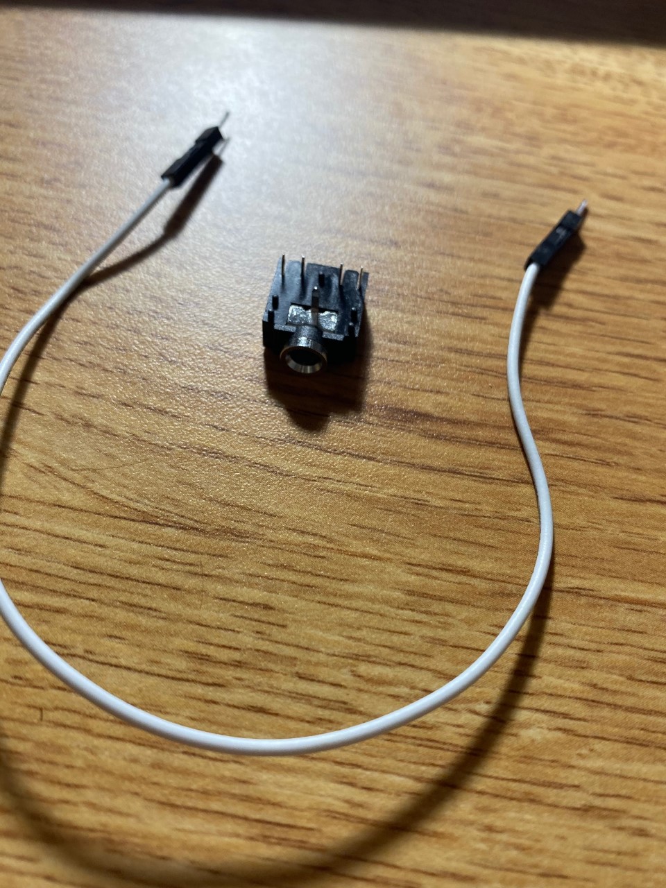
I had a quick question about general audio electronics. I am trying to take an input from an aux cord, and use this output to be put into the arduino's analog input. However, I can't figure out how to read in the output from the aux. I have a 3.5 mm audio jack that I attached down below, and I have tried touching jumper wires to the certain pins to see if any input is taken in, but I have came up empty-handed. I would really appreciate any help on how to have an aux plugged into a phone or speaker and take its output from the aux and input it into the analog pin of my arduino. Thanks.
Hi,
Are you aware that the analog input is only DC, not AC as would be the case with audio.
It is possible but more than just a plug into the aux socket and connection to the controller analog input is needed.
What do you want to do with the audio once you have it going to the arduino?
Can you tell us your electronics, programming, arduino, hardware experience?
Sorry about the whole mishap on the pictures, I am new to the forums. I'm trying to follow this tutorial (LED-Music-Visualizer-Without-Freq-Converter/README.md at master · echan42/LED-Music-Visualizer-Without-Freq-Converter · GitHub) on a LED music visualizer. The project explains that I need to hook up an audio source to the analog pin. I knew that audio was AC, and that the arduino only takes DC, so I was trying to use a diode that would turn the AC into DC. However, I can't test if my circuit is working because I can't receive any input from the audio jack. What I'm trying to do is receive the analog input from the aux, and map this input to different colors and wavelengths for my LEDs. I am trying to follow this guy's tutorial, but I don't know if it makes sense. Any help would be appreciated on letting me know if this project is even possible, and if it is, how I am able to get an input from an aux into the analog pins in a correct way. Thanks.
Hi,
Does your aux, that you are getting audio from have that socket?
If so you will need a plug to fit it?
The gnd of the plug will go to gnd of the Arduino.
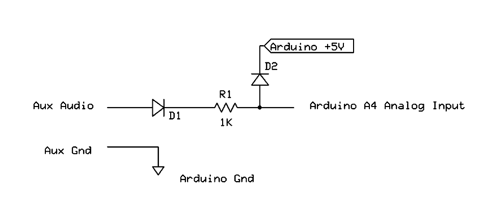
The signal connection of the plug will go via a diode to the Arduino A4 INPUT.
Something like this.
D1 rectifies the input, R1 and D2 protect the Arduino analog input from overvoltage.
Feel free to comment or suggest changes to this basic circuit.
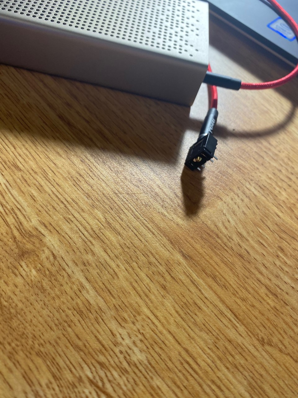
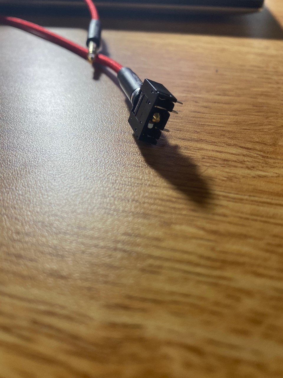
Thanks so much for the diagram, that really helps visualize everything. I understand everything that is on the diagram, except the aux audio and aux ground part. I am still confused on how I'm able to gain those inputs from the aux cord. For the plug question, I have attached two pictures down below to show that I have an aux plug that I will connect to a speaker and then into the audio jack. Now, my next question is how do I get the aux audio and aux ground from this connected system. Do I have to find a way to get my audio jack plugged into a breadboard, and then use jumper wires to pull the aux audio and connect the grounds from the audio jack pins? If this is not the case, I would appreciate any suggestions on how to do this. Once I can figure that out, I think I can do everything else on my own. Thanks so much for the help. I really appreciate it.
Hi,
So you have a cord that has a 3.5mm plug on each end.
Now you want to connect the socket you have in the picture to the arduino.
Do you have a DMM?
You will have to work out which pins on the socket connect to which contacts on the plug.
Can you post a link to data/specs of the socket, or where you purchased it?
I do have a DMM available to me. I have followed this website (Connector Basics - SparkFun Learn) to try and figure out which pins correlate to what connection on the plug. I tried following the audio jack example by touching my jumper wires to the specified pins earlier, but this still seemed to cause no input. The way I did this was had a ground wire touching the middle pin (the sleeve pin) and another wire that touched the leftmost pin (the tip pin) to try and get an aux input. However, this didn't seem to do anything, so that's where I have been stuck. Since I have a DMM available, can this help me determine which pins are connected to what? Also, I bought the jack from amazon (https://www.amazon.com/gp/product/B07MFKKWG5/ref=ppx_yo_dt_b_asin_title_o00_s00?ie=UTF8&psc=1).
TomGeorge:
Hi,
Gnd is the sleeve of the plug, the tip and ring will be the stereo L and H channels.
Tom...
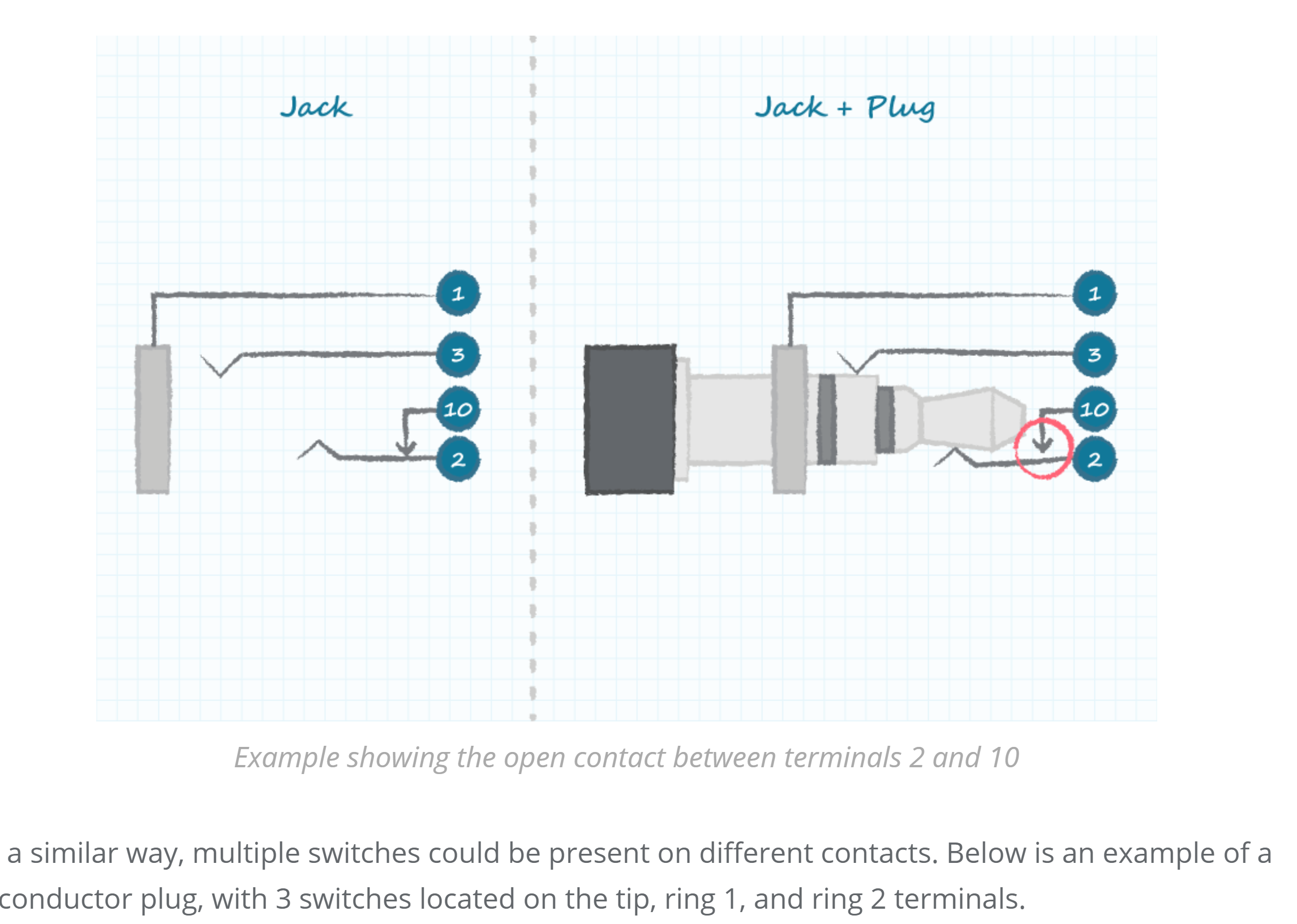
Hi, I have studied the data sheets and basics of the audio plug. I now understand that my audio jack has five pins labeled L, SL, SR, R, and C. However, I am still confused on how to hook these pins up into my circuit. I do not know how to connect wires to the audio jack to deliver an input into my circuit. I'm attaching the pictures below to give you a schematic of what my exact audio jack is like.
I now understand that my audio jack has five pins labeled L, SL, SR, R, and C. However, I am still confused on how to hook these pins up into my circuit.
The "extra" switched connections are not needed. They are for speakers, so when you plug-in headphones the speakers get switched-off.
Just plug-in a male connector and check/confirm the connections with your Ohmmeter.
What I'm trying to do is receive the analog input from the aux, and map this input to different colors and wavelengths
There are two issues with the diode technique. You're distorting the waveform and that messes-up the frequency* information. And, you get a voltage drop of about 0.6V across the diode so weak signals won't come-through.
The most common solution is to bias the input at 2.5V so the audio signal can go positive & negative relative to the bias. You can either subtract-out the bias in software or with FFT/FHT you can simply ignore the zero Hz bin. There is a schematic for the bias circuit at the bottom of my post [u]here[/u].
Or, if you only need 7 frequency bands you can use an [u]MSGEQ7 chip[/u] which takes care of the DC bias issue and makes your software a LOT easier.
With audio electronics we talk about frequency instead of wavelength. Wavelength is related to acoustic sound waves in the air (0r it can be related to radio frequency signals).
Thanks of the info. I had a quick question. What happens if I build this circuit. This is a frequency meter. Would this erase the problem of having the audio distorted? I already have all the parts for this setup, so I would like to refrain from having to buy new parts like the chip unless I have to. If this circuit does work, I had a quick question about the photo. On the part where the audio jack is shown (picture down below), their is two wires coming out from the audio jack. I'm assuming this is the ground and analog input signal. However, how would I do this for the audio jack that I explained above. Would I have to solder some wires to the actual pins of the audio jack deliver the analog input and ground into the circuit?
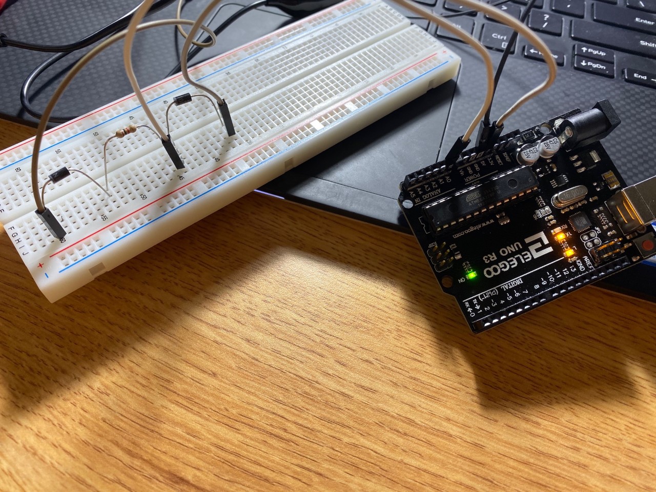
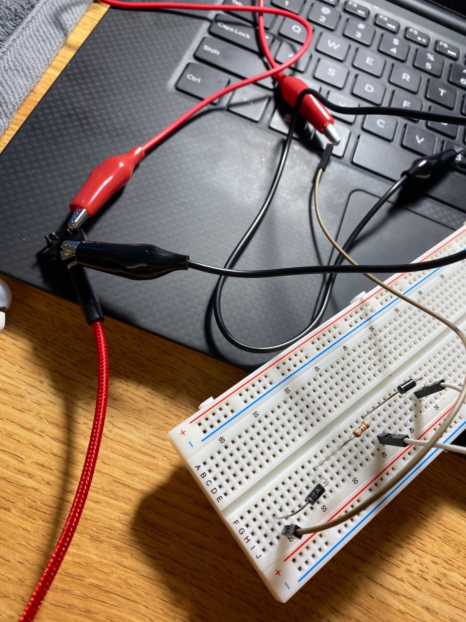
Hi, over the past couple hours, I have tried experimenting with the help that was given. I was successful in one thing. I was able to hook up my audio jack to an oscilloscope and DMM to see that their was indeed an audio output coming from my phone. That solves my issue with figuring out how to get audio into my circuit. However, I have ran into a new problem. I built the circuit that was provided above, and I attached pictures down below. I wanted to run a quick test that read in the analog input to see if it changed when I was playing music. However, as the photos show, the analog input was constantly at 4.25 volts with nothing changing. I don't know why this is happening. Based off the circuit, the analog input should be varying based off the audio signal. Would anyone please let me know what I am doing wrong, so I can try and fix my problem. Also, in the circuit, I tried using 1N4001 and 1N4004 diodes, but the result was still the same. Thanks.
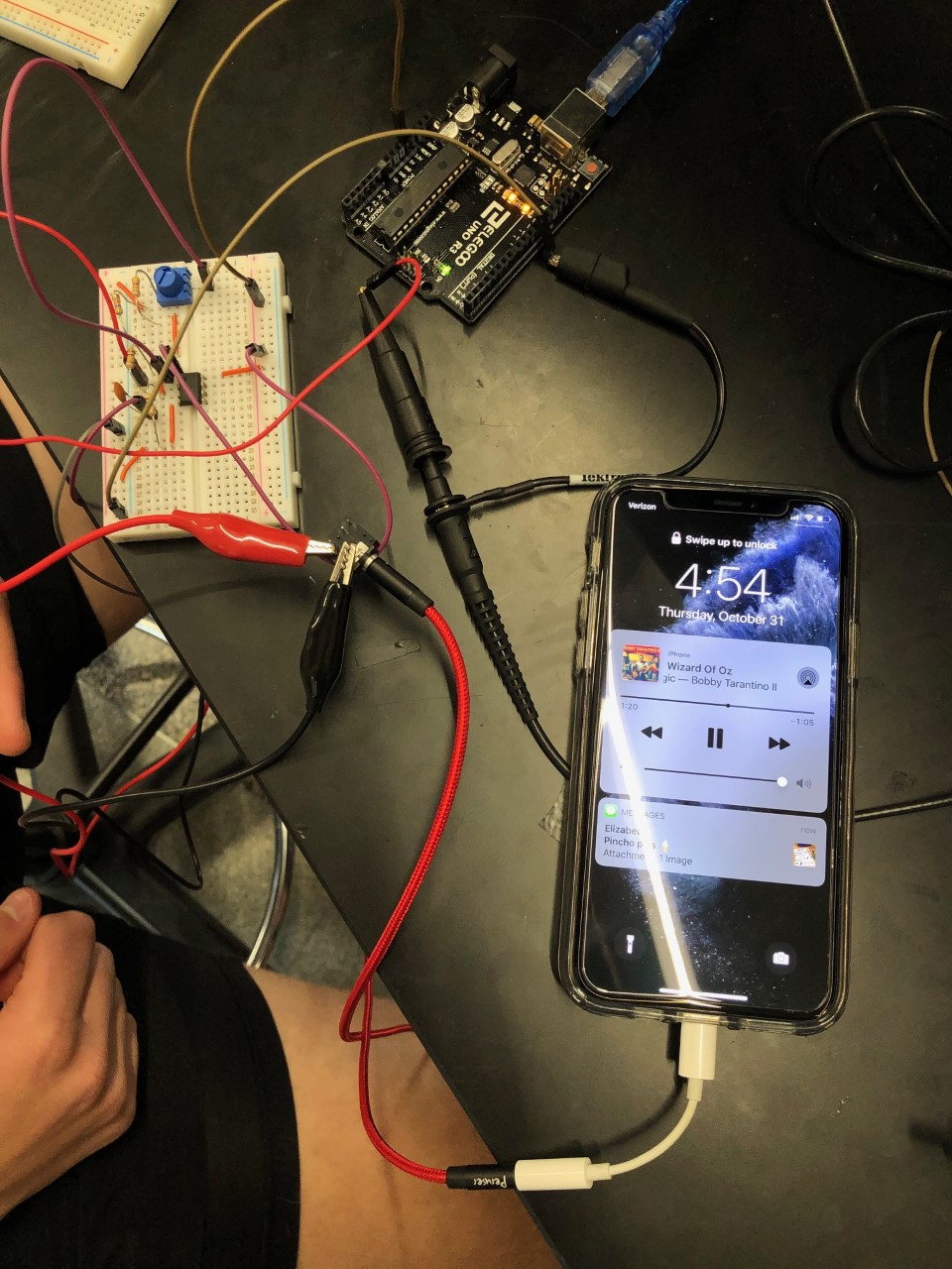
I built the frequency meter that I had attached above. I then hooked up the oscilloscope to see what was being measured by the audio input to the analog A0. I attached the results for the oscilloscope below. What it shows is that there is a wave that changes with the frequency of the music, but the wave only peaks around 1.2 to -1.2 volts. Also, when I stop the music, the oscilloscope would nearly flat line showing that the music was indeed being inputted. However, whenever I actually plug the analog pin into A0, I would never receive a changing analog input like I had posted about above. If anyone could help me on this problem, I would greatly appreciate it. I was just wondering why my arduino is not reading the change in audio input, even though the oscilloscope is showing an audio reading.
Why don't you get an app for your phone that just outputs a tone, not music, that way you can see if you are looking at noise or signal?
OR
Use a AF signal generator to produce you audio signal for setup purposes?
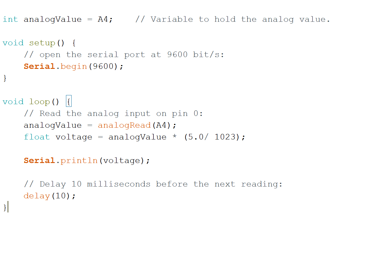
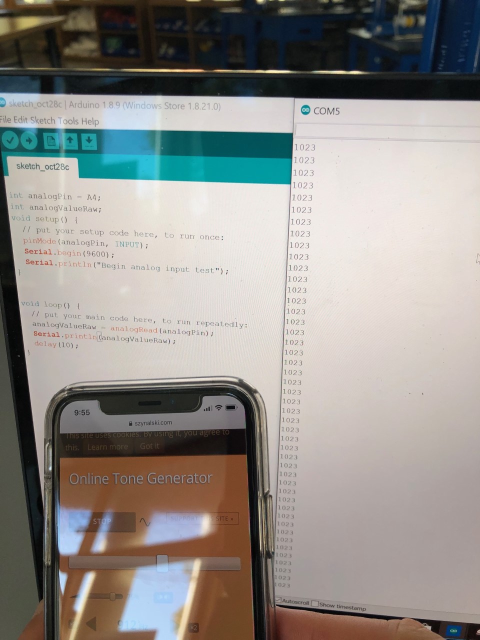
I attached the simple code that I was using down below. I can try downloaded an app and seeing if it is noise or not. I have two questions about that. If it is noise, why might that be the case? If it is actually reading a voltage input like I think it is, how come the analog pin won't update? Thanks so much for the help.
Hi
Try this code, you code is using the pin number as the analog read number.
int analogPin = A4;
int analogValueRaw;
void setup() {
  // put your setup code here, to run once:
  pinMode(analogPin, INPUT);
  Serial.begin(9600);
  Serial.println("Begin analog input test");
}


void loop() {
  // put your main code here, to run repeatedly:
  analogValueRaw = analogRead(analogPin);
  Serial.println(analogValueRaw);
  delay(10);
}
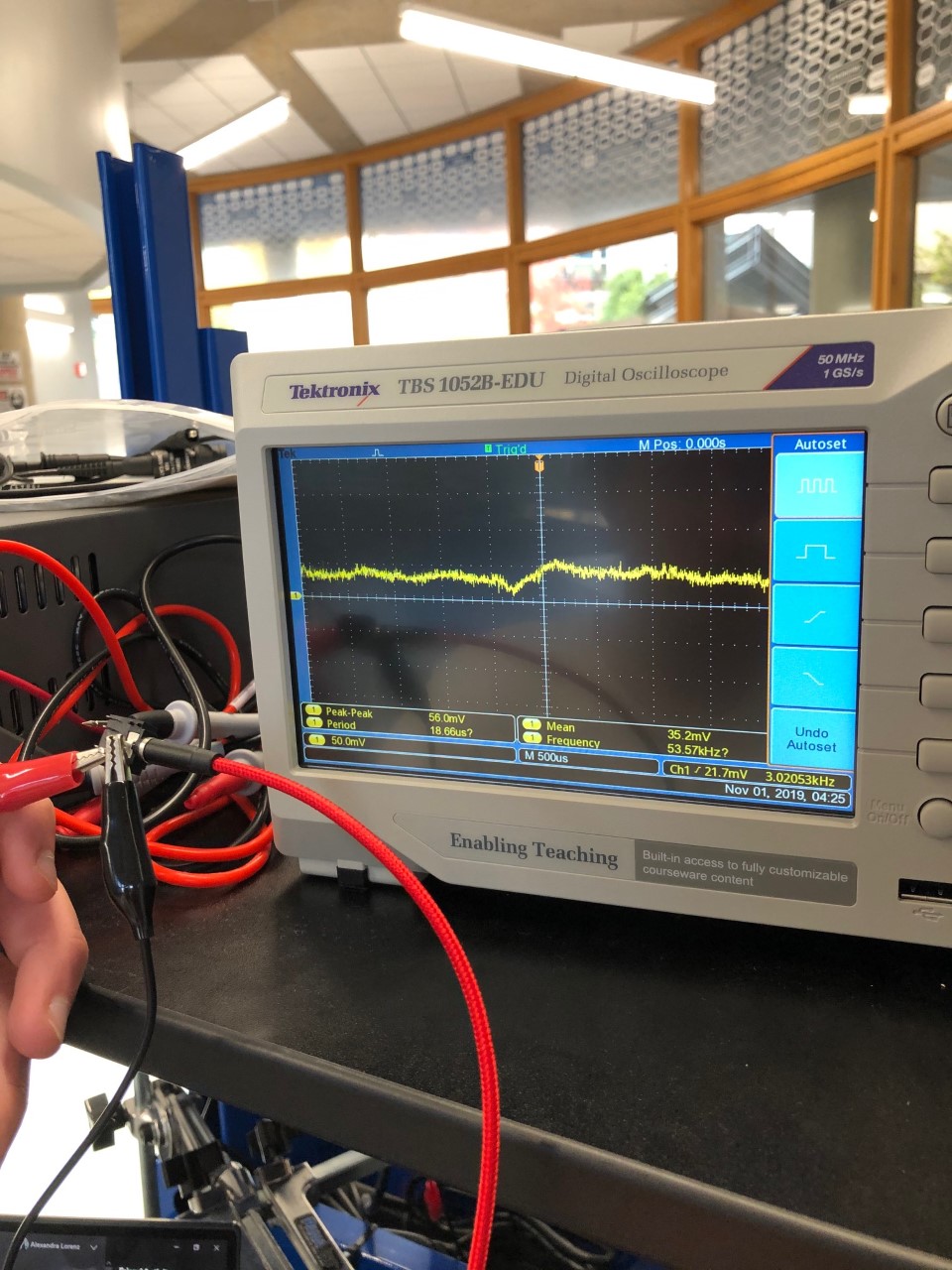
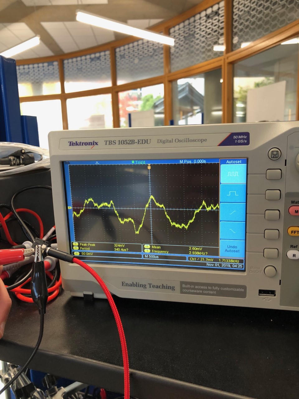
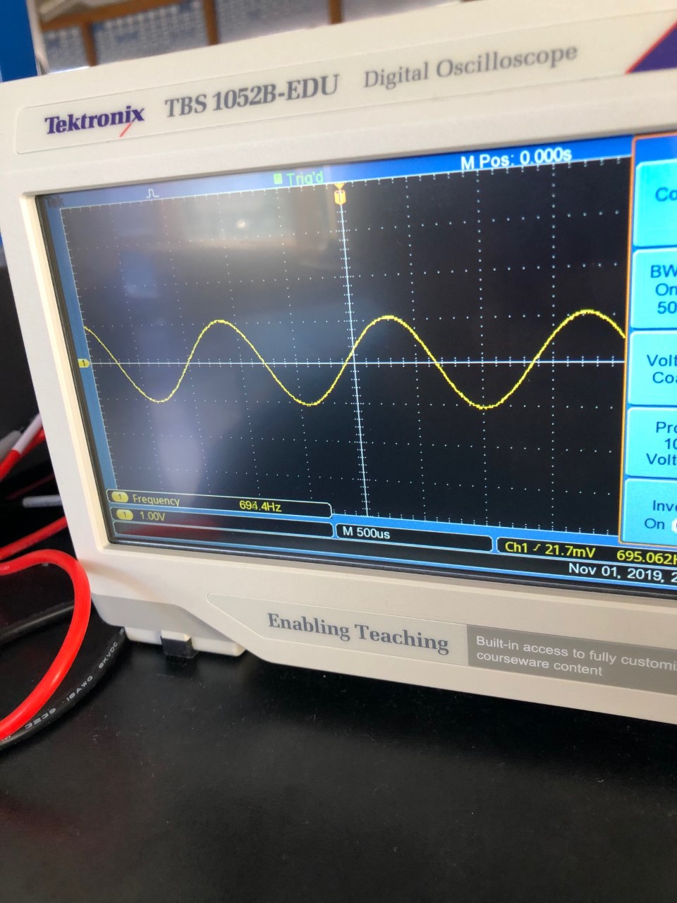
I tried the code that you had sent, and I also tried using a constant frequency. The results are shown down below. There was three things that happened. When the oscilloscope was hooked up straight to the audio jack and a constant frequency was played from my phone, the resulting wave was a perfect sine wave that matched the frequency. However, when I hooked up the oscilloscope to my circuit and played a constant frequency, the wave (as shown below) was jagged and was not a perfect sine wave. I do not know what is happening there; however there is still an audio signal being read in (not just noise). Then, after changing my code to yours and plugging in my frequency circuit, the analog pin consistently read in 1023 despite me changing the input frequency. This is still the main problem that I am having. The analog pin doesn't seem to be reading the input from the aux cord.