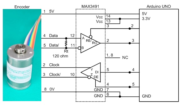
How to Read Data SSI Encoder

const int CLOCK_PIN = 4; // Blue Pin
const int DATA_PIN = 3; // Green Pin
const int CS_PIN = 8; // Yellow Pin
const int BIT_COUNT = 24; // 24 Bit Mode

const int DATA_ENABLE_PIN = 2;
const int DE_PIN = 5;

void setup(){

pinMode(DATA_PIN, INPUT); pinMode(CLOCK_PIN, OUTPUT);
pinMode(CS_PIN, OUTPUT);
pinMode(DE_PIN, OUTPUT); pinMode(DE_PIN, LOW);
pinMode(DATA_ENABLE_PIN, OUTPUT); pinMode(DATA_ENABLE_PIN, LOW);
digitalWrite(CLOCK_PIN, HIGH); digitalWrite(CS_PIN, HIGH);

Serial.begin(115200);
}

void loop()
{
float reading = readPosition();
if (reading >= -0.5)
{
Serial.print("Reading: ");
Serial.println(reading, 2);
}
delay(1000);
}

//read the current angular position
float readPosition()
{
// Read the same position data twice to check for errors
unsigned long sample1 = shiftIn(DATA_PIN, CLOCK_PIN, CS_PIN, BIT_COUNT);
unsigned long sample2 = shiftIn(DATA_PIN, CLOCK_PIN, CS_PIN, BIT_COUNT);
delayMicroseconds(20); // Clock must be high for 20 microseconds before a new sample can be taken
if (sample1 != sample2) return -1.0;
return ((sample1 & 0x0FFF) * 360UL) / 4096.0;
}

//read in a byte of data from the digital input of the board.
unsigned long shiftIn(const int data_pin, const int clock_pin, const int cs_pin, const int bit_count)
{
unsigned long data = 0;

digitalWrite(cs_pin, LOW);
for (int i = 0; i < bit_count; i++)
{
data <<= 1;
digitalWrite(clock_pin, LOW);
delayMicroseconds(1);
digitalWrite(clock_pin, HIGH);
delayMicroseconds(1);

data |= digitalRead(data_pin);

}
digitalWrite(cs_pin, HIGH);
return data;
}

  • Reading: 359.91 (Serial monitor)
    Only the above values continue to appear. It doesn't work properly. What the reason?

Please post a datasheet in English.

The wiring diagram does not show how the encoder is powered.

@jremington

Thank you for answer.
Please send the datasheet in English.
EPM50_English.pdf (317.1 KB)

The power supply is applying 12V.

@jremington

No matter how much I think about it, I don't know what's wrong.

just a quick look, don't you mean

digitalWrite (DE_PIN, LOW);

this seems to be a better datasheet:
https://www.acotron.com/download/f1e043260331e4700b581b854bbaed5c_EPM502.pdf

and base of the info in it, I think you may have any issue with the voltage levels if you are using a MAX3491 (operates at 3.3V)

image

I would suggest you try to use a different RS485 driver. something like this one for example.

OR... have a go with this sample code from this thread on the same topic!

hope that helps....

I find it odd that the code is using Pin 8 but the schematic doesn't show it attached to anything.

Unfortunately, the OP never came back to say if they tried the code or if it worked. That code is probably completely untested.

@gcjr
@sherzaad
@johnwasser

Thank you very much for your reply.

Maybe a chip
Can I change 'MAX3491' to 'MAX491'?

Please review.

I will change the chip and test it with the example source code you provided.

might work....

@sherzaad
@gcjr
@johnwasser
@jremington

const int DATA_PIN = 2;
const int CLOCK_PIN = 3;
const int RE = 4;
const int DE = 5;
const int REESET = 6;
const int DIR = 7;

void setup()
{
//setup our pins
pinMode(DATA_PIN, INPUT);
pinMode(CLOCK_PIN, OUTPUT);
pinMode(RE, OUTPUT);
pinMode(DE, OUTPUT);
pinMode(REESET, OUTPUT);
pinMode(DIR, OUTPUT);

digitalWrite(RE, LOW);
digitalWrite(DE, LOW);
digitalWrite(REESET, HIGH);
digitalWrite(DIR, HIGH);

Serial.begin(115200);
}

unsigned long ReadEncoder()
{
unsigned long encoderData = 0;

digitalWrite(CLOCK_PIN, LOW);
digitalWrite(CLOCK_PIN, HIGH);
for (int i = 0; i < 24; i++)
{
encoderData <<= 1;
digitalWrite(CLOCK_PIN, LOW);
encoderData |= digitalRead(DATA_PIN);
digitalWrite(CLOCK_PIN, HIGH);
}
return encoderData;
}

void loop()
{
unsigned long enc = ReadEncoder();

if (enc & 0x00800000) // Bit 24 is the overflow bit
{
Serial.println("Overflow");
}
else
{
float revolutions = enc / 1024;
Serial.println(revolutions, 4); // Display to 4 decimal places
}
delay(500);
}

It doesn't work.
Is there any way..? help.

thank you sm

  1. datasheet url :
    https://forum.arduino.cc/uploads/short-url/qFE8N7U5WuOenCKzYlw6FUwCkXU.pdf
    https://forum.arduino.cc/uploads/short-url/lsrVDY2ydzYBz7SkXYI001v2Npz.pdf

  2. circuit image :


    a3

I ran tests with 3 different chips, but didn't get the desired results.
I tried 3 ways, but couldn't get the result.
Why? help me.

@sherzaad
@gcjr
@johnwasser
@jremington
@gnownee

This is a problem with the firmware source code.

  1. It is a delay problem of digitalWrite / digitalRead.
  2. To solve this problem, 'FAST' function was used.
  3. So, I solved it.

(1) Circuit
DATA+ 4
DATA- GND
CLOCK+ 7
CLOCK- GND

(2) Firmware

const int DATA_PIN = 4;
const int CLOCK_PIN = 7;
digitalPinFast pinTest(DATA_PIN);
digitalPinFast pinTest2(CLOCK_PIN);

unsigned long ReadEncoder(){
unsigned long encoderData = 0;
delay(1); digitalWrite(CLOCK_PIN, HIGH);
for (int i = 0; i < 14; i++)
{
if(i>0){encoderData <<= 1;}
pinTest2.digitalWriteFast(LOW);
delayMicroseconds(1);
pinTest2.digitalWriteFast(HIGH);
delayMicroseconds(1);
if(i>0){ encoderData |= bitRead(PIND, 4); }

}
return encoderData;
}

Thank you for leaving a reply.
Thank you for caring me. have a good day.