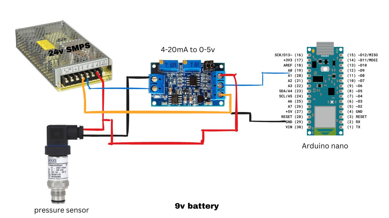
I am currently working on a project using a pressure sensor with Arduino Nano. The pressure sensor gives a 4-20mA analog signal, so I have used a 4-20mA to 0-5V converter and connected its output to the A0 pin of the Arduino Nano. However, the Arduino is showing random values between 0-1023 instead of consistent readings. Could you please guide me on how to resolve this issue?
Please provide me communication diagram for connection with Arduino, pressure sensor, SMPS , 4-20mA to 0-5v convertor .
The easiest way to read the 4-20 mA signal is to use the analog input and a resistor, either 250 Ohms with a 5V ADC reference voltage, or 51 Ohms with the 1.1V ADC reference voltage.
sir please tell me how I will do it, convertor is working well, This converter has a supply voltage range of 7–30 Vdc.
please tell me about my wiring connection
Have you actually measured the 4-20mA loop with a meter?
Have you measured the output of the converter with a meter?
Have you calibrated zero and span?
Instructions for use:
The module according to the definition of wiring, power supply voltage 7-36V (if the output to 10V, the supply voltage must be greater than 12V).
After power-up, the D2 indicator should be on, otherwise check the line connection. Board with reverse protection, the reverse does not burn.
When the current input is the minimum (0mA or 4mA), adjust the ZERO potentiometer so that the VOUT output is the minimum (0.0V or other voltage).
When the current input is at maximum (20mA), adjust the SPAN potentiometer so that the VOUT output is the maximum (3.3V or 5V or 10V, the output can be as low as 2.5V when the input is 4-20ma).
According to your needs, through the jumper cap to select the appropriate range:
Jumper Settings for Output Voltage RangeInput Signal: 4-20mA
1.0-2.5V: J1 1,2 pin are short circuit connected; 3, 4 pin are short circuit connected
2.0-3.3V: J1 1,2 pin are disconnected; 3, 4 pin are disconnected
3.0-5V: J1 1,2 pin are short circuit connected; 3, 4 pin are short circuit connected
4.0-10V: J1 1,2 pin are short circuit connected; 3, 4 pin are disconnected
Jumper Settings for Output Voltage RangeInput Signal: 0-20mA:
1.0-3.3V: J1 1,2 pin are short circuit connected; 3, 4 pin are short circuit connected
2.0-5V: J1 1,2 pin are short circuit connected; 3, 4 pin are short circuit connected
3.0-10V: J1 1,2 pin are short circuit connected; 3, 4 pin are disconnected
yes , i have measured 4-20mA with a multimeter
and output 0-5v with a multimeter, i don't know my serial monitor is showing random value between 0-1023.
i probably have done mistake in my wiring. please correct me
yes , i have measured 4-20mA with a multimeter
and output 0-5v with a multimeter, i don't know my serial monitor is showing random value between 0-1023.
i probably have done mistake in my wiring. please correct me
// Initialize the LCD with the I2C address 0x27
LiquidCrystal_I2C lcd(0x27, 16, 2);
void setup() {
Wire.begin();
Serial.begin(9600);
while(!Serial);
Serial.println("\n I2C Scanner");
// put your setup code here, to run once:
lcd.init();
// Turn on the LCD backlight
lcd.backlight();
}
void loop() {
// put your main code here, to run repeatedly:
int sensorvalue = analogRead(A1);
// float x = 102.0;
// float scaled = (sensorvalue)/x;
Serial.println(sensorvalue);
// Set the cursor to the first row, first column
// lcd.clear();
// lcd.setCursor(0,0);
Hi,
Lets do some troubleshooting.
Remove the converter form the Nano.
Short A1 to gnd, what reading do you get?
Connect A1 to 5V what reading do you get?
I'm working on the same problem and gave up on the signal converted. There is so much confusion on how to wire it and not have the arduino power draw affect the loop current signal.
Instead I switched to using a 250 ohm resistor to convert to 1-5V. 165 ohm for 1-3.3V.
The "trick" for me was to jumper the arduino ground to the "negative" on the loop circuit. Otherwise i'd get a sine-wave esque type deal going on jumping from 0V to 5V.
Vref of a classic Nano on USB supply is about 4.6volt (not 5volt), and not stable, which throws your readings off. It would be better to use a 52 Ohm resistor, and switch Aref to the more stable internal Aref of the Nano. That makes readings independent of USB supply variations.
2* 100 Ohm in parallel gets you close enough to 52 Ohms.
Leo..