the serial input is like this
[index][value]
example : 10
example : 51
example : 31
this should be taking the first digit and using that to decide where to edit the array and the second one should be saying what to set the array elements value to.
#include <LiquidCrystal_I2C.h>
int counter;
int SET=1;
int READ=0;
int value;
int relays[]={0,1,0,0,1,0,0,0};
LiquidCrystal_I2C lcd(0x27,20,4);  // set the LCD address to 0x27 for a 16 chars and 2 line display
//setup---------------------------------
void setup(){
  Serial.begin(9600);

  // initialize the lcd
  lcd.init();
  lcd.backlight();
  //set pin modes
  pinMode(2, OUTPUT);
  pinMode(3, OUTPUT);
  pinMode(4, OUTPUT);
  pinMode(5, OUTPUT);
  pinMode(6, OUTPUT);
  pinMode(7, OUTPUT);
  pinMode(8, OUTPUT);
  pinMode(9, OUTPUT);
  Serial.println("Device Ready");
}

//functions------------------------------
int editPin(int mode, int pin, int val){
  int out;
  if(mode==0){
    if(digitalRead(pin)==HIGH){
      out=0;
    }else{
      out=1;
    }
    return out;
  }else{
    if(val=="0"){
      digitalWrite(pin,HIGH);
    }else{
      digitalWrite(pin,LOW);
    }
  }
}

//actual stuff---------------------------
void loop(){
  char ch = Serial.read();
  if(ch >= '0' && ch <= '9'){
    value = (value * 10) + (ch - '0'); // yes, accumulate the value
  }else if (ch == 10){
    // String Name = value;
    relays[int(String(value).charAt(0))]=int(String(value).charAt(1));
    Serial.print(int(String(value).charAt(0)));
    Serial.print(int(String(value).charAt(1)));
    Serial.print("|");
    Serial.println(relays[String(value).charAt(0)]);
    for (counter=0;counter<8;++counter) {
      Serial.println(relays[counter]);
    }
  }
  for (counter=0;counter<8;++counter) {

    editPin(SET,counter+2,relays[counter]);


    lcd.setCursor(counter,0);
    lcd.print(editPin(READ,counter+2,0));
  }


}
I suspect I will need to fully redesign that code, but I dont know how and I have been at this for 3 days, I think I just need someone to help me since I have no idea what I'm doing at this point.
Read in chars from Serial like this. You have all the ASCII set of keys on your keyboard and put them in a switch/case to do specific things like this:
  if (Serial.available() > 0) {
   char input = Serial.read();
    Serial.println(input); // optional, for debugging. That's for us to read, not Arduino
    switch (input){
      case '1':
      var = 11; //just happens to activate my NES controller servo control
      break;
      case '2': // arbitrary ASCII key
      // do something else
      break;
    }
  }
Note that these are chars, not ints like some sensor value. It's literally for using standard keyboard presses to do stuff.
By the way, what values? Sensor readings? Keyboard presses? What?
The more specific you are, the better help we can give.
EDIT: I just realized I had declared char input globally in the code I got this from, so I added it in here for clarity and utility.
I generally like to input the full line of text before processing it. See Serial Input Basics for examples of how to do this.
Using the 2nd example from the link, its just a matter of turning the ASCII character into a number for the array index and the value, provided you stay within the limits of single digits for each:
// Example 2 - Receive with an end-marker

const byte numChars = 32;
char receivedChars[numChars];   // an array to store the received data

boolean newData = false;

void setup() {
  Serial.begin(9600);
  Serial.println("<Arduino is ready>");
}

void loop() {
  recvWithEndMarker();
  showNewData();
}

void recvWithEndMarker() {
  static byte ndx = 0;
  char endMarker = '\n';
  char rc;

  while (Serial.available() > 0 && newData == false) {
    rc = Serial.read();

    if (rc != endMarker) {
      receivedChars[ndx] = rc;
      ndx++;
      if (ndx >= numChars) {
        ndx = numChars - 1;
      }
    }
    else {
      receivedChars[ndx] = '\0'; // terminate the string
      ndx = 0;
      newData = true;
    }
  }
}

void showNewData() {
  if (newData == true) {
    newData = false;
    if (strlen(receivedChars) == 2){ //verify that exactly two characters were received
      //probably a good idea to verify both characters are numbers and within allowable values
      int relay = receivedChars[0] - '0';
      int value = receivedChars[1] - '0';
      Serial.print("Input: ");
      Serial.print(receivedChars);
      Serial.print("\trelay:");
      Serial.print(relay);
      Serial.print("\tvalue:");
      Serial.println(value);
    }
  }
}
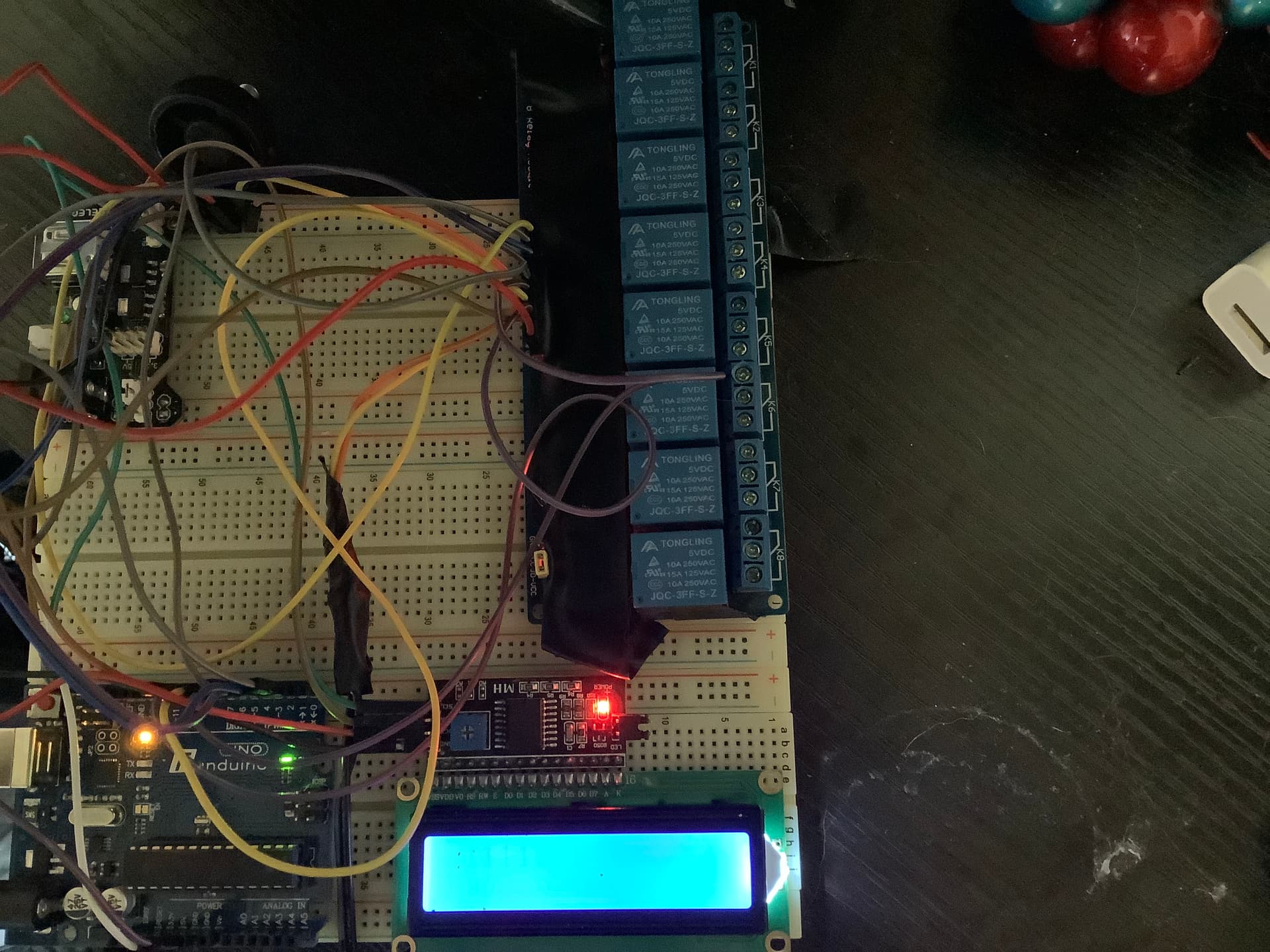
Your "schematic" says "LCD controller", but your picture shows an output device only. It looks like a replacement for the Serial monitor, just info for you to see what you input to trigger one or all of the relays.
What are you wanting to type in? Words like "turn lights on"?
Would simple chars do it? '1' for on, '0' for off? 'r' 'g' 'b' for colors, '+' or '-' to increase and decrease control values?
also, you do know that relays don't go "brr" when they are operating correctly, right? There's a click when you use them to turn something on or off, that's it.
[relay number][value]
value will turn the relay on and off by being either a 1 or a 0
and relay number specifies the pin that the relay is on, with on offset of +1
Yes, the relays have been clicking and acting perfectly fine, I was just commenting on how when enough of the relays turned on the LCD display got dim.
Let me guess, they're 5V relays powered from the Arduino 5V pin. If so, don't do that, provide external 5V from a USB charger or other wall wart.
Other than that, here's an idea - label the relays 'A' to whatever. Turn relay A on if you receive a capital A, off if you receive a lower case 'a'. No need for anything more complicated.
It's dead simple, easy to remember, and you get away from 0 and 1, which can become a problem when you install a different relay board who's logic is inverted from the one you have right now.