I have a couple of Arduino Nanos here and for my current project I'd need to start up the Nano immediately when powered (no boot time, if possible).
I tried to follow this video to connect two Nanos (removing the Bootloader and using one to program the other) but ran into a problem:
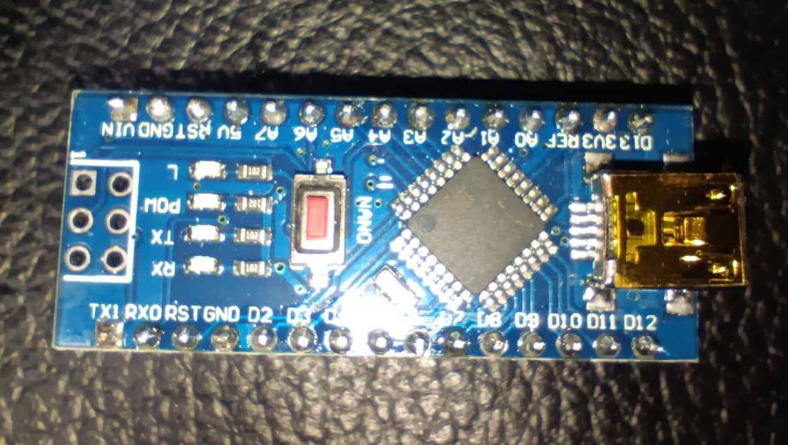
Most Nanos show the writing "ICSP" next to those six pins that are used to do so. Mine do not (see photo). Do these pins have the same functionality as shown in the video then or do I have to use any other pins instead?
I also couldn't find examples of using two Nanos, there always seem to be at least one Uno involved - is this mandatory or can this be done with two Nanos as well?
The 6 pins are the ICSP header but note that each of the pins is connected to another pin on the board which can be used instead
You can remove the bootloader by uploading a sketch using the ICSP pins and a programmer
More correctly, that does not remove the bootloader but stops it being invoked on subsequent resets, so there is no waiting to see whether a sketch is going to be uploaded using the serial interface which is what causes the delay
You can use one Nano to program another as in most respects the Nano and Uno are functionally equivalent
If the nano is using the current boot loader (not the “old boot loader”) there should not be much delay. The first thing the boot loader does is check to see if the processor was reset from a power up, and if so goes immediately to the user sketch.
I would just say that in my experience the bootloader does not cause any material delay unless USB is actually connected. If it is connected, there will be a negotiation, but otherwise I think it just goes directly to your sketch. But you can test that.
If you ICSP upload code to the AVR, it will remove the bootloader.
i.e. there will no longer be a bootloader and a application, there will only be an application and the reset vector will jump to the gcc startup code in the sketch.
If you are using the optiboot bootloader, which I think you are, then the bootloader does not cause delay on powerup or watchdog reset.
The first thing it does is check to see if the AVR is starting up from a power up or a reset. If it is not a pin reset it will jump directly to the application code (your sketch).
If it is a pin reset, then the bootloader will flash the on board LED an then monitor the serial port for an upload. After 1/2 second it will jump to the application code.
You can test this by looking at the on board LED and see the behavior difference when you power it up vs reset it by pushing the reset button.
If all you want/need is a fast startup from a power up, you essentially already have it. I say "essentially" because there are few instructions that do get executed,
I'd have to look at the actual bootloader code but I'd guess that it is going to be on the order of 1us
So if you eliminated the bootloader you would only save about 1us on powerup or watchdog reset.
On reset, yes, it would make a difference but not much on powerup.
@david_2018: I uploaded a picture of my wiring - see post #6. No, I did not add a capacitor - I've never seen that in the diagrams I've seen so far. Is this mandatory? What type of capacitor should be used?
@bperrybap: No, I am not using Optiboot firmware - both Nanos are common ATMega china clones with old bootloader, as far as I know. All I want is a quick startup (current boot time is ~2.5 seconds)
Bill, you know much more than I do about these things, but is the bootloader actually removed by the process of uploading using ICSP or is it more accurate to say that after such an upload then the bootloader code is not executed on startup ?
Experiments uploading the same code via Serial and ICSP show that using ICSP does not make any more memory available.
You uploaded a diagram of how the wiring should be, I was requesting a picture of the actual boards and wiring, to see if you had made any mistakes.
The capacitor generally is around 10uF, and goes between the reset pin and ground on the arduino that is being used as the programmer. The purpose is to prevent the arduino from resetting if the computer resets the serial connection during the programming process.
@david_2018 : Do you mean a capacitor between D10 (wich is connected to RST on the target) and GND or RST (wich is not used on the programmer) and GND? That's a bit confusing for me.