Thank you very much
If you use:-
// set up fast sampling mode
  ADCSRA = (ADCSRA & 0xf8) | 0x04; // set 16 times division
In the setup function then the Uno can run at about 36K sps ( samples per second ) without any loss of accuracy.
This works by making the A/D converter's clock run faster by adjusting the pre scaler division ratio.
1 Like
tested UNO analogueRead() using code
[code]
// test analogueRaed() on Arduino UNO

int analogPin = 0;
void setup()
{
  Serial.begin(115200);          //  setup serial
  // set up fast sampling mode
  // ADCSRA = (ADCSRA & 0xf8) | 0x04; // set 16 times division
}

#define SAMPLES 500
int data[SAMPLES] = {0};
int index = 0;

unsigned long currentMillis = millis();
void loop()
{
  if (index >= SAMPLES) return;     // if acquisition complete return
  long int timer = millis();    // start timer
  while (index < SAMPLES)           // acquire 400 samples
    data[index++] = analogRead(analogPin);  // read the input pin
  timer = millis() - timer;     // acquisition time
  for (int i = 0; i < SAMPLES; i++) // print samples for plot
  {
    Serial.println(data[i]);
  }
  return;       // required for plot - comment out for following print
  Serial.print("Time for 500 samples ");
  Serial.print(timer);
  Serial.print("mSec  ");
  Serial.print(SAMPLES * 1000L / timer);
  Serial.println(" Samples per second");
}
[/code]
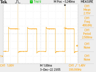
Test signal = 400Hz period 2.5mSec
run of above program prints Time for 500 samples 55mSec 9090 Samples per second
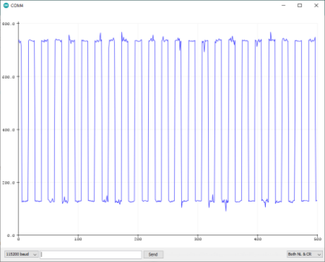
check acquisition time approx 22 cycles time = 22*2.5 = 55mSec
suggestion by @Grumpy_Mike make A/D converter's clock run faster by adjusting the pre scaler division ratio
test - uncomment the following line in above program
  // set up fast sampling mode
  ADCSRA = (ADCSRA & 0xf8) | 0x04; // set 16 times division
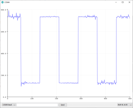
Result –Time for 500 samples 7mSec 71428 Samples per second
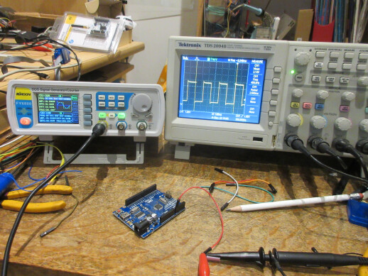
check using oscilloscope cursor 2 – cursor1 = 7.6mSec = 65789 samples/second
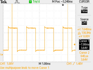
test setup
do the calculations for samples/second make sense???
Yes they do.
it looks as though the UNO could acquire data as specified in the original requirements in post #1 and #5, e.g.
I have to collect sensor output data (198 sample) at 19.8 milliseconds period only in arrays .
probably interrupt at 0.1mSec intervals and call analogRead() in the ISR
when 189 samples acquired loop() can process them
not sure from post #5 if acquiring Array1 is concurrent with Array2 or Array1 is acquuired then Array2
198 sample of First cycle of analog signal I have to collect in one array after that again in second cycle I need to collect 198 sample in another array.so one by one as outputs cycle come I need to capture signal in array.


After 0.2 milliseconds I need to start array and in 19.8 milliseconds I need to capture data in array 1 and after that again cycle repetition starts So again
I need to start array in 19.8 milliseconds.is it possible??
Array 1 is acquired than array 2, i have to collect samples
This is my sensor output which I am reading on serial monitor through analog input on pin A0. Actually I have to reduce noise of this sensor output signal so I am collecting it in array and after that I have to do averaging. so that I could detect original signal Peak.
Your two topics on the same or similar subject have been merged.
Please do not duplicate your questions as doing so wastes the time and effort of the volunteers trying to help you as they are then answering the same thing in different places.
Please create one topic only for your question and choose the forum category carefully. If you have multiple questions about the same project then please ask your questions in the one topic as the answers to one question provide useful context for the others, and also you won’t have to keep explaining your project repeatedly.
Repeated duplicate posting could result in a temporary or permanent ban from the forum.
Could you take a few moments to Learn How To Use The Forum
It will help you get the best out of the forum in the future.
Thank you.
After ALL these posts yu STILL have not said what the sensor is, what it is measuring, how it is connected, what part of the signal is significant ... (is it the peak amplitude of the spike?)
why are you so reluctant to give us information that will let us help you?
Sensor is chemical agent detector. Sensor output pin is connected to Arduino analog pin and sensor' s ground is connected to Arduino ground.Actually this is giving just air peaks when chemical is not present and as soon as it detects any presence of chemical it gives just some small peaks beside Air peak signal .noise is also present in this signal.So i just need to remove noise so that if any chemical presence is detected,our sensor could give alarm.To remove noise I have to do averaging of signal and for averaging i have to collect this analog signal.i have mentioned in my post through sensor output signal image that after 0.2 milliseconds I need to collect sample in 19.8 milliseconds duration now could you suggest what should I do?
can you provide a link?
How will you identify the small spike that marks the start of the 20ms period? Do you have access to the timing signal that you show in your sketch?
@Grumpy_Mike in post #22 showed how make A/D converter's clock run faster by adjusting the pre scaler division ratio
post #23 presented the results of some tests which showed that using the technique the UNO ADC could sample approximatly 65000 samples/second
I suggested in post #25 after detecting the pulse interrupt at 0.1mSec intervals and call analogRead() in the ISR - when 189 samples acquired loop() can process them
have a look at arduino Timer interrupts tutorial
here is an example of using UNO Timer1 to interrupt every 0.1mSec and blink LED every second
// timer1  interrupt every 0.1mSec blink LED every second

#include <TimerOne.h>
volatile bool timerTriggered = false;
const int LED_pin = 13;

void setup() {
  // put your setup code here, to run once:
  Serial.begin(115200);
  Timer1.initialize(100); //Initialize timer with .1 mSec second period
  Timer1.attachInterrupt(printFunc);
  pinMode(LED_pin, OUTPUT);
  digitalWrite(LED_pin, LOW);
}

void loop() {
  static long timer = millis();   // used to check time
  // put your main code here, to run repeatedly:
  if (timerTriggered) {
    Serial.print("Timer was triggered ");
    Serial.println(millis() - timer);
    delay(1);
    timerTriggered = false;
    digitalWrite(LED_pin, !digitalRead(LED_pin));
    timer = millis();
  }
}

// called on timer1 interrupt
void printFunc(void) {
  sei();                          // enable interrupts
  static int count=0;
  if(count++ >=10000) {
    count=0;
  timerTriggered = true;
  }

}
a run gives
10:23:02.472 -> Timer was triggered 999
10:23:03.485 -> Timer was triggered 998
10:23:04.503 -> Timer was triggered 1000
10:23:05.486 -> Timer was triggered 998
10:23:06.499 -> Timer was triggered 1000
10:23:07.505 -> Timer was triggered 999
Is your pulse train EXACTLY in synch with the sample signal? If so what maintains that synchronisation? Is it like a gas chromatograph where a trigger event intitiates a process during which your data is collected?
Taking two successive mesurements into arrays and averaging them will not greatly reduce your noise. The "traditional" way to deal with data like this (if your data can be repeated quickly enough) is to gather a series (maybe 64) of timed samples into "bins".
You may also wish to look at the characteristics of your noise signal; perhaps it ISNT noise, but a consistent feature of the system - in which case you can do a run in the presence of your sample, and subtract the data taken in the absence of the sample.
This topic was automatically closed 180 days after the last reply. New replies are no longer allowed.