Can you please review the attached wiring schematic for a shed? Any suggestions for improvement? How would you do it if was your shed?
The shed is brand new. My son and I built it this summer. He's 16 and I'm trying to teach him something about wiring. And programming.
The goal is to keep the shed "off the grid." So far, we have a 12V marine battery, and light fixtures — indoor and outdoor. Plus an Arduino Uno that we'd like to program, so it schedules the lights on after dark, and turns them off in the morning.
Future plans include more 12V lighting and solar panel(s) to charge the battery, but I'll reserve that for a future post.
For now, can you please help us schedule the lights on and off. So, two things:
Wiring Diagram / Circuit Drawing, and
Sketch
Thank you in advance for your help in this regard.
It is best not to power the Arduino with 12V. Instead, use a step-down 5V regulator, such as this one, and connect the 5V output to the 5V pin.
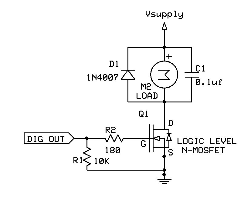
The most energy efficient way to switch the lights with an Arduino is to use a logic-level N-MOSFET, as shown in the circuit below (substitute the light for "M", a motor. D1 and C1 are not needed).
Edit: kind of a repeat of jremington but a bit of added info.
I would advise to not power the Arduino through the Vin or the power jack. Powering through Vin or the power jack means that the Arduino and all peripherals that are on the 5V rail are powered by the onboard 5V regulator. The on board 5V regulator is not heat sinked so will supply limited current before it overheats and shuts down. The recommend max power dissipation for the regulator is 1 Watt. With 12V into the regulator the max current is about 140 mA (1W / (12V - 5V)). The Arduino uses around 50ma of that leaving less than 90mA (max) for everything else. I would use a buck converter to drop the 12V to 5V and connect that to the 5V on the Arduino, bypassing the, weak, 5V regulator.
jremington & groundFungus - Thank you! I searched the components that you suggested and translated what you said into a revised wiring diagram. Can you please review Version 2 attached and let me know if I understood you correctly?
BTW - jremington, I hear you: It makes more sense to turn on the lights only if it is dark, and someone is inside. But the shed is also a garden feature, complete with stained glass that glows beautifully in the dark — when the shed is lit on the inside. Might try it your way when the novelty wears out.
You will need a proper charger, one that maintains a float voltage even when the circuit is off, and a battery protection/automatic shutoff circuit to avoid drawing the battery voltage too low.
You should never discharge a "12V" lead acid battery below 10.5V. More info here and at batteryuniversity.com.
groundFungus - Thank you. I revised the wiring diagram per your latest reply. Please see Version 3 attached.
jremington - Thank you. Does the Noco Genius G750 qualify as a proper charger? Please see attached image. As for battery protection, any suggestions? I mean do you have something in mind? And where do I put it on the wiring diagram?
BTW - Do either of you do this for a living? We're happy to pay for design services. Can you also write an Arduino Sketch for this project? Might be best if you contact me privately... bright_guy@mac.com
The Arduino can monitor the battery voltage and for example, refuse to turn on the lights if the voltage drops below 10.8V or so. There are lots of battery monitor posts on the forum.
Noco Genius G750?
That is a trickle charger, intended for charging very small batteries, and only maintaining larger ones. The charger you choose depends on how large the battery is and how quickly you want to recharge it. You should learn about the Ampere-hour (Ah) measure of battery capacity, as it will be very important in choosing your lights and battery.
This is an idea generation/problem solving forum section. If you want to hire someone to help with the design, post on the Gigs and Collaborations forum section.
The OP said that you would use the Arduino to schedule turning lights on and off. Would that be a certain times of day? The Uno is not a very precise timekeeper. You might want to think about adding a Real Time Clock (RTC) to keep time of day. The DS3231 is a popular RTC and is widely available on RTC modules.
groundFungus:
The OP said that you would use the Arduino to schedule turning lights on and off. Would that be a certain times of day? The Uno is not a very precise timekeeper. You might want to think about adding a Real Time Clock (RTC) to keep time of day. The DS3231 is a popular RTC and is widely available on RTC modules.
Thank you. Yes, the original concept was to control the lights for certain times of day. Might consider light sensor, but for now I'll research the DS3231 RTC that you suggested. Will revise the wiring diagram accordingly.
jremington:
There are lots of battery monitor posts on the forum.
Thank you. I will search the forum. Sounds like added hardware is not required. If it is, or if revisions to the wiring diagram are required, I will make them and post them here shorty.
jremington:
That is a trickle charger, intended for charging very small batteries, and only maintaining larger ones. The charger you choose depends on how large the battery is and how quickly you want to recharge it. You should learn about the Ampere-hour (Ah) measure of battery capacity, as it will be very important in choosing your lights and battery.
Thank you. We already bought the lights and battery. Our plan is to charge the battery as required. If the battery monitor does what it's supposed to, we'll know when the battery requires a charge because the lights will be off. Not the most sophisticated plan, I know. But I'm sure we'll redesign with experience and as we learn more about battery capacity as you suggest.
jremington:
This is an idea generation/problem solving forum section. If you want to hire someone to help with the design, post on the Gigs and Collaborations forum section.
Thank you. We'll check out that section shortly. But this morning I feel like we can do this ourselves, especially with the help of this community.
To monitor the 12V battery voltage you must drop the 12V (actually over 12V while charging) to less than the 5.5V maximum allowed into an input pin. That is usually done with a resistor voltage divider circuit. If we assume the max voltage will be 15V or less while charging the circuit below would work (using standard 5% resistors). Calibration with a DMM (Digital MultiMeter) would make it accurate. The cap is optional.
groundFungus:
To monitor the 12V battery voltage you must drop the 12V (actually over 12V while charging) to less than the 5.5V maximum allowed into an input pin. That is usually done with a resistor voltage divider circuit.
The resistor voltage divider has been added — thank you groundFungus. Just not sure where to connect Signal Ground?
Also, an RTC module has been added. Not sure if I wired it correctly?
Please see attached updated wiring diagram.
Next Steps?
Purchase parts — RTC module, voltage regulator, N-MOSFET output module
Signal ground should be connected to Arduino (and all other) grounds. Try not to daisy chain grounds. It is best that they all terminate at the same point (star grounding).
The RTC looks to be connected properly. Just make sure that the RTC module can be supplied by 5V and the SDA and SCL signals are 5V compatible. The DS3231 is a 3.3V device so the module needs to have a voltage regulator 5V to 3.3V and level shifters or you must supply them.
Also, I was planning to connect "all other grounds" to the marine battery's negative terminal. Hope that's OK.
groundFungus:
Just make sure that the RTC module can be supplied by 5V and the SDA and SCL signals are 5V compatible. The DS3231 is a 3.3V device so the module needs to have a voltage regulator 5V to 3.3V and level shifters or you must supply them.
The DS3231 was suggested a few days ago on this thread. Was that suggestion made in error? The DS3231 looks ok to me because the specs say, "Operating Voltage: 3.3 - 5.5 V." Am I missing something?
Do I connect the Signal Ground to the Arduino as illustrated here?
Yes that is fine.
Also, I was planning to connect "all other grounds" to the marine battery's negative terminal. Hope that's OK.
Yup, that is good, too. "All other grounds" includes the Arduino ground.
That RTC looks good. I mentioned the potential problem with supply and signal voltage cause I bought a couple DS3231 modules that only worked on 3.3V and popped one when I connected to 5V before I realized that they were 3.3V only. Just wanted to make sure that you knew of the potential problem.
Do not try to write the whole program at once. Separate it into several tasks. Write code for each task. Then it will be easier to plan the final program and combine the parts once each part is understood. The Planning and Implementing a Program tutorial may be useful. You may need to do some timing in your code. You probably know that delay() is not the best way to do so. Here are some good tutorials on using millis() for timing: Several things at a time. Beginner's guide to millis(). Blink without delay().
groundFungus:
That RTC looks good. I mentioned the potential problem with supply and signal voltage cause I bought a couple DS3231 modules that only worked on 3.3V and popped one when I connected to 5V before I realized that they were 3.3V only. Just wanted to make sure that you knew of the potential problem.
Sorry, I didn't know that some DS3231 modules only worked on 3.3V. I'll be sure to watch for that when we're shopping for 5V modules.
Also, I appreciate the guidance for programming. Thank you!