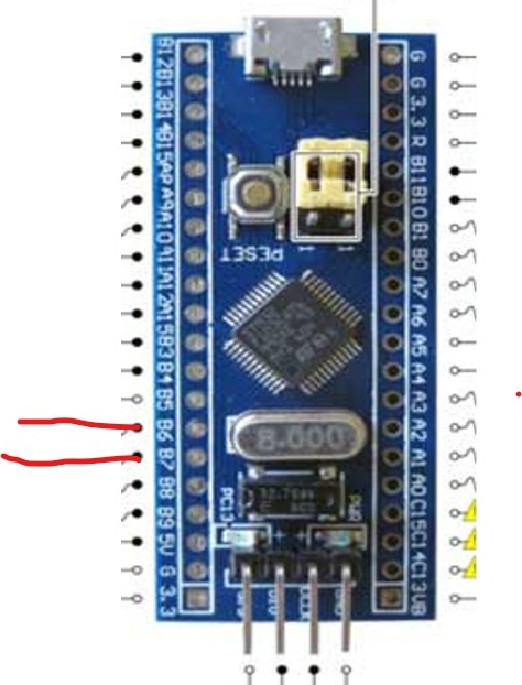
this is the circuit diagram
Uploading: Screenshot 2022-07-11 105754.jpg...
Uploading: Screenshot 2022-06-25 132021.jpg...
i can't trigger the interrupt it keeps running in the main loop although it is high or low
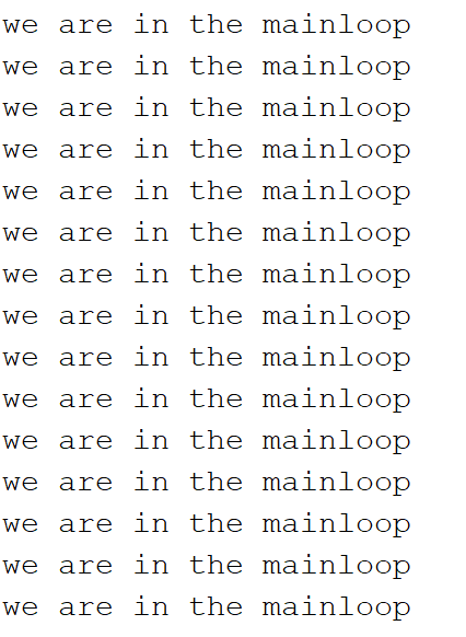
when the switch is at the middle position this is the output
here is the code
//INTERRUPTS IN STM32F103C8

//CIRCUIT DIGEST

                                   //  variable declared as global

//PB3 TOGGLE switch

void setup()


{


  attachInterrupt(digitalPinToInterrupt(PB3),buttonPressed,CHANGE);                      //  function for creating external interrupts


}


void loop()                                                       //  void loops runs continuously

{
  Serial.println("we are in the mainloop");
  delay(10);
 }


void buttonPressed()                                              //

{
 Serial.println("interupt triggered ");

}
this is the circuit diagram
b707
4
please clarify what do you expect from the code
gcjr
5
is PB3 a pin # that digitalPinToInterrupt() recognizes or simply a register address?
Not a good idea to serial.print in the ISR.
b707
7
PB3 is a macro returning pin#
As you can see the code should print interrupt triggered when it is triggered else it should keep running in the main loop i hope you can understand
I changed already yet the same thing
PB4 is a digital pin that accept interupt whether you use the digitaltointerrupt or not
Or sorry I wanted to say PB4
b707
12
Do not use Serial.print in the interrupt handler. By the test replace the printing by the led blinking on some pin and try again.
Ok good i would use that instead
it is not working this is the new code
//INTERRUPTS IN STM32F103C8

//CIRCUIT DIGEST                               //  variable declared as global

//PB3 TOGGLE switch
int ledPin = PB4;

void setup()
{ pinMode(ledPin, OUTPUT);
  pinMode(PB3, INPUT);

  attachInterrupt(digitalPinToInterrupt(PB3),buttonPressed,CHANGE);                      //  function for creating external interrupts


}


void loop()                                                       //  void loops runs continuously

{
  Serial.println("we are in the mainloop");
  //delay(10);
 }


void buttonPressed()                                              //

{
 //Serial.println("interupt triggered ");
 digitalWrite(ledPin, HIGH);

}
Your board diagram shows the input on PB7,PB6 not PB3.
b707
16
what's mean "not working" ?
and try to change interrupt pin to PB0, for example... PB3 is "special" pin
no is an error it is PB3 INPUT AND PB4 for output
b707
21
this code works for me
(board - STM32F103C8 "bluepill")
int ledPin = PC13;  // PC13 = LED built-in at bluepill
uint8_t irq_pin = PB0;
void setup()
{ pinMode(ledPin, OUTPUT);
  pinMode(irq_pin, INPUT_PULLUP);
  attachInterrupt(digitalPinToInterrupt(irq_pin),buttonPressed,CHANGE);                      //  function for creating external interrupts
}
void loop()                                                       //  void loops runs continuously
{  }

void buttonPressed()                                              //
{
 digitalWrite(ledPin, !digitalRead(ledPin));
}