Hi,
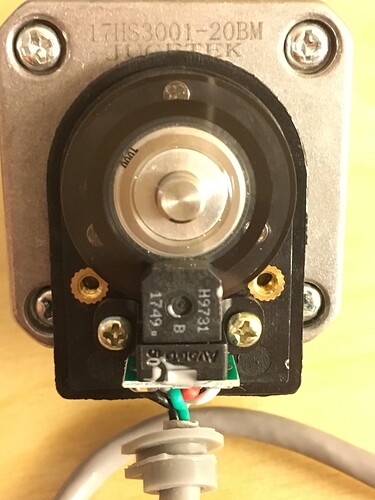
I am trying to use a stepper motor w/rotary encoder, but am having trouble getting a useful signal from the encoder. After some research, I have determined the rotary encoder is an Avaga HEDS 9731, link below.
I have tried directly wiring VCC to 5V, GND to GND, A to pin 2, and B to pin 3 with no luck.
I can see in the datasheet that they recommend a Load Capacitance of 100pF, and there is a note about using 3.2 kOhm pull-up resistors, but I cannot seem to figure it out.
Can someone please suggest a wiring diagram and potentially some basic code (less important) to get this working?
Thank you
Connect a 3.3k resistor from pin 2 to 5V, another 3.3k resistor from pin 3 to 5V, Vcc to 5V, gnd to GND. Post the code you are using and tell us what works or not.
I tried including the 3.3kOhm resistors, but still no luck.
I have attached an image of my circuit so you can verify everything is connected properly.
I have also included the code I am using for testing. The result is nothing appears on the serial monitor. Turning encoder by hand results in nothing.
/*     Arduino Rotary Encoder Tutorial
 *
 *  by Dejan Nedelkovski, www.HowToMechatronics.com
 *
 */

 #define outputA 2
 #define outputB 3
 int counter = 0;
 int aState;
 int aLastState;
 void setup() {
   pinMode (outputA,INPUT);
   pinMode (outputB,INPUT);

   Serial.begin (9600);
   // Reads the initial state of the outputA
   aLastState = digitalRead(outputA);
 }
 void loop() {
   aState = digitalRead(outputA); // Reads the "current" state of the outputA
   // If the previous and the current state of the outputA are different, that means a Pulse has occured
   if (aState != aLastState){
     // If the outputB state is different to the outputA state, that means the encoder is rotating clockwise
     if (digitalRead(outputB) != aState) {
       counter ++;
     } else {
       counter --;
     }
     Serial.print("Position: ");
     Serial.println(counter);
   }
   aLastState = aState; // Updates the previous state of the outputA with the current state
 }
Looks like you may have Vcc and channel B reversed, but can't tell without seeing the device, can you post well lit and focused pictures of front and back, showing connections and terminal markings / pin numbers? Also a pic of your code wheel.
If you don't have Paul Stoffregen's encoder library, use library manager in the Arduino IDE or download here and give it a try.
I don't think I have Vcc and channel B reversed, but maybe. I downloaded that library, and ran the basic example, still no luck.
I have attached several pictures (had to make two posts due to file size), let me know if you need me to retake them, or try to take a pic of something else.
Add this to your setup():
pinMode(LED_BUILTIN,OUTPUT);
Add this to your loop():
digitalWrite(LED_BUILTIN,digitalRead(2));
See if the LED blinks when you turn the wheel VERY slowly. Then try pin 3.
So when using "digitalWrite(LED_BUILTIN,digitalRead(2));" the LED is off, always.
When using "digitalWrite(LED_BUILTIN,digitalRead(3));" the LED is on, always.
I found some additional information on the exact encoder I am using, which may be helpful.


