for the insufficient accuracy for Temperature readings (and strongly connected Humidity readings...) there were several workarounds blaming cheap Chinese sensors (which is not true) adding offsets, make calibration routines.... but the basic problem is that the HS221 is placed just next to the (2nd) most heat generating component
The integrated power supply brick is its warm neighbor having a load-depending efficiency at USB between 55% and 95% so fixed offsets etc dont match here....
is there a proper solution (or hardware redesign?) i want to measure room ambient temperature - not the status of the power supply
this variation in T messes up the Humidity value completely since the relativeH% is very strong depending on T
P.S: the parts are cool at specs and component level - the HTS221 as well as the MPM3610 but board design is very poor. A 40€ piece of electronis is not cheap (even if u could put 400€ on a professional T sensor....) but if you want to to it properly place the T sensor to a corner of the board and maybe even invest 50 Cents in thermal insulating by some milling around
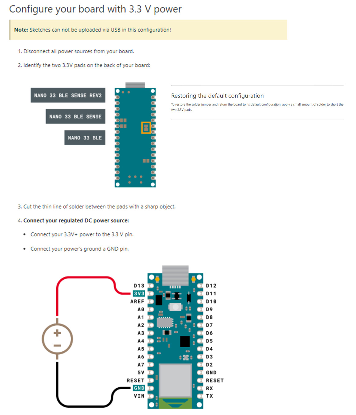
To obtain reliable measurements, the board shall be powered by the 3v3 pin, this could be done by cutting the +3V3 solder jumper on the bottom and powering the board through the VIN pin
Or you could use an external temperature sensor; eg, a separate HTS221...
Yes, that would be the "proper" design, but look at the board - where is there space to do that?
thank you very much - fast and helpful answers in 10 min (y)
the 'jumper' is the 2 connected pads next to pins A2 and A3?
about place issue - true as well but does it make sense to put as many components to the board even they wont work then just to have them there and get some readings for nothing?
I think the prime purpose of the temperature sensor in these things is for its own internal use in its primary function as a humidity sensor - they only make it externally accessible as a "free bonus".
So, if you want accurate/precise temperature, you'd be better off with a dedicated temperature sensor anyhow.
I guess its a cool learning board for programming classes at school maybe to focus on software and what u can get from real world to ur code with minimal hardware and efforts
but for any engineering application get a old school nano + 3€ dedicated sensor for the application
okay dont expect automotive grade documentation but jea many things read 'hmm try it but mind of an fire extinguisher close by'
OK - back to the topic - I cut the 3.3V labled jumper on backside - connected 3.3V supply to 3.3V pin (not VIN as in FAQ) and it works - T is 4°C lower (and H is some % higher) which reads very reasonable to me now
thank you @awneil for this productive solution finding