here is what I am working on (forgive me if it is not finished, I have only had my first Arduino for about a week)
A humidity and temperature sensor network:
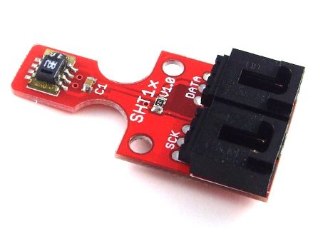
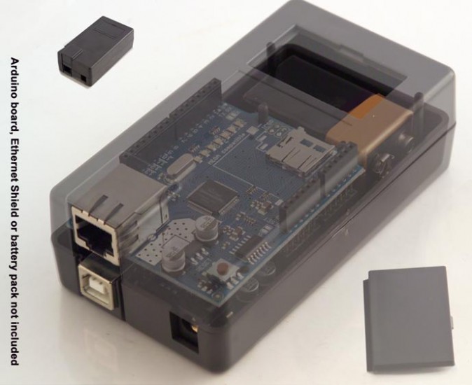
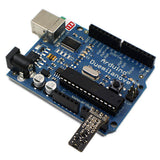
Every node consists of an Arduino board and an ethernet shield and a Sensirion SHT15 Humidity and Temperature Sensor on a breakout board. I will use the enclosure that accomodates an Arduino, an ethernet shield and place the sensor in the battery box. That makes for nice, compact nodes.
and
Exhibition means what u have done ,not what u dream of.
here is what I am working on (forgive me if it is not finished, I have only had my first Arduino for about a week)
I'll forgive you. I can't say that anyone seems to put stuff in the right forum ever anyway. I just get it all amalgamated into my reader feed so I can't say I care.
By the way, have you had a look at the JeeNode design? It is arduino-compatible (except it is running at 3.3V, but the software doesn't care). They've got a huge number of small sensor "plugs" available including temperature and humidity. Price for a JeeNode kit is less than an assembled Arduino, and it includes wireless as well! (915 MHz band in the USA, 868 MHz in Europe). I have three JeeNodes now and they work very nicely for a home sensor network. Check out this blog, it's pretty impressive: http://jeelabs.org/ In the US, you can get the kits from http://shop.ModernDevice.com
Disclaimer: No financial interest, I'm just a customer. Enthusiastic one, though
From the www.practicalarduino.com example, I get
Temperature: -40.0099983215C / -40.0180015563F. Humidity: -4.69%
From the Arduino playground example, I get
Temperature: 0.0 C, Humidity: 0.0 %, Dewpoint: 0.0 C
I don't know if the sensor is broken or if it is a software problem.
I wouldn't mind getting a sensor that just works. In the case of the link that you sent, they sell a Humidity and Temp Sensor that can be pluged directly into the Arduino board AND the library can be downloaded from a link on the same web page. That way, I know that I get the correct software for that hardware.
I am not sure into which forum this topic would fit. It would be nice if there were a forum for planned and ongoing projects. Such a forum would allow people such as myself to discuss project ideas and to get input regarding the choice of hardware (as seen here).
I can't tell for sure but those look like solderless breadboard jumpers connecting your sensor. Hopefully you've soldered them to the sensor board and not just shoved them in the holes, right?
The photo of the Sparkfun sensor in your original post shows R1 and R2 unpopulated. You need a 10K pullup on the data signal (R1). Does your board have one installed?
Finally, make sure you've correctly modified the example code to use the pin numbers you have wired to the data and clock signals.
I would think it unlikely your sensor is bad but it is always possible. Good luck!
By the way, I should note, the JeeNode "Sensor Plug" modules are intended to plug into a JeeNode which is running at 3.3 V only, and also arranges the pinouts in a different way physically (same pins coming from the AT328P CPU, but going in different places). I think some, maybe most of the Jee sensors are not designed for +5V logic level, which is what the regular Arduino uses. Note also, the ModernDevice.com website sells some JeeNode system modules and some other, more generic sensors so you need to pay attention to the logic level requirements.
I haven't looked at either the hardware or the code, but is it true, at least on some pins you can set an internal pullup resistor (maybe 20k or so?) using some software selection?
you are correct - there could be a 'Project in Progress' section.
I've used the Practical Arduino code, and a -ve value represents an error. (I think he mentions this in the source code).
Double check your connections. Also be sure that you are using the pin specified in the code.
you are correct - there could be a 'Project in Progress' section.
Well I think the issue is that people will start a project and it might take a number of months between progress updates/before the finish it so you'd just end up with a forum subsection full of half finished projects.
I haven't looked at either the hardware or the code, but is it true, at least on some pins you can set an internal pullup resistor (maybe 20k or so?) using some software selection?
Yes, you can enable internal pullups on the Arduino I/O pins (write a "1" to the pin with it in INPUT mode) but they are spec'd to be between 20K and 50K ohms. The Sensirion sensor spec recommends 10K. You might be able to use the internal pullups if you change the library code to slow down the clock to the sensor but it could take a bit of work to prove reliable operation.
there are SMD resistors R1 and R2 on the board-that's what you meant, right?
I did solder the cables, checked conductivity, and verified +5V on the board. I also made sure that I am using the correct DIO pins: 10 and 11 for the practialarduino.com example, and 2 and 3 for the Arduino playground example.
and the page says: "It has a 4-pin interface that can communicate directly with the analog pins on the Arduino."
Well- in two days I'll know: the sensor is already in the mail being shipped to me.
I also ordered a sensor from China. They have a sensor shield and a sensor module that is plug-ready,
there are SMD resistors R1 and R2 on the board-that's what you meant, right?
Yes, that's what I meant. The photo in your original post didn't have them and I couldn't tell in the later photo. Do you have good connections at the Arduino end of your jumpers? I've seen the sockets get a little loose over time. Otherwise, double check your pins vs. the example code - maybe try different pins and changing the code correspondingly.
The Modern Device sensor uses an SHT21 (I2C interface) so it requires different software than the SHT1x based boards (or SHT7x).
Their example PDE says: " * Tested with the SHT21-Breakout
Humidity sensor from Modern Device."
If that doesn't work, then... >:( :-[
So you think one of the DIO ports may be belly-up? I was thinking about building a diagnostics shield with a bunch of LED's and push-buttons, some analog inputs (potentiometer?) for a quick board test.
To make it even simpler, is it possible to directly connect one digital port to another and configure one as output, the other as input, write on one and read on the other, and then switch their roles to test the input and output function of both with the same wire?
So you think one of the DIO ports may be belly-up?
Hopefully not! I mostly suspect a faulty connection of some sort but changing to different pins might help rule out a flaky port. Do your jumper wires fit snugly in the Arduino sockets? I assume you are using the example code from one of the libraries unchanged (eg, SimpleSensirion with the Playground library) or with just the pin assignments modified.
Re: the SHT21 - I just wanted to be sure you knew it required different software than the others.
I tested pins 2 and 3 for input as well as output capabilities and they work.
I have downloaded the library Sensirion_04Aug10.zip from http://www.arduino.cc/playground/Code/Sensirion#SHT1x
and tried NonBlocking as well as SimpleSensirion. I have also tried pin 5 and 6 and still no luck. The software returns some values, but these values are constant no matter what I do to the sensor. At this point, I am out of ideas and have contacted customer support.
Re: the SHT21 - I just wanted to be sure you knew it required different software than the others.
And it is very much appreciated. I hope to get that sensor on Monday.
Why would you want to use multiple Arduinos? A 1-Wire network is much easier to set up and you can have multiple 1-Wire buses on 1 Arduino. I use a Mega and read 6 1-Wire devices plus monitor my electric usage and control my X10 stuff. All the data is sent to my PC as a comma delimited string and displayed using a VB program I wrote... just curious.


 and a sensor module that is plug-ready,