Humidity sensors, PWM fans + 2 arduinos

Hello, this is my first project, which I started 2 years ago. Unfortunally I havent worked on it for the last year. While some knowledge I have learned in the past is still there, I have forgotten some also. I thought this might the moment to ask help.

I want to make a system which reads out the tempature and humidity in and outside my greenhouse and if needed it starts fans or bumps up the speed of the fans.
I already managed to have a Leonardo controling a relais with a fan while reading out 2 BME280 sensors. But this was on a small scale and before being able to scale it up I accidentally broke both sensors.
So I bought new sensors and finalized my plan, but before I connect anything, I would like to know if someone can point out what mistake I'm about to make. Because there's going to be at least one mistake, that is obvious, but it would be nice if from here on my 'Arduino problems' would be coding problems, those are cheaper and easier to fix.

When I read the rules or tips before posting on this forum, I noticed it stated not to use Fritzeng diagrams. I thought by myself, that can't be a problem, since I don't know what that is. The only diagram I use is the one I made myself about a year ago.
Then I got curious about what a Fritzeng diagram is...
So yeah... I'm very sorry. It helped me a lot, within a minute I remembered what ports I wanted to connect between the different modules. Again: not made in Fritzeng, but I am sorry for this inconvenience.

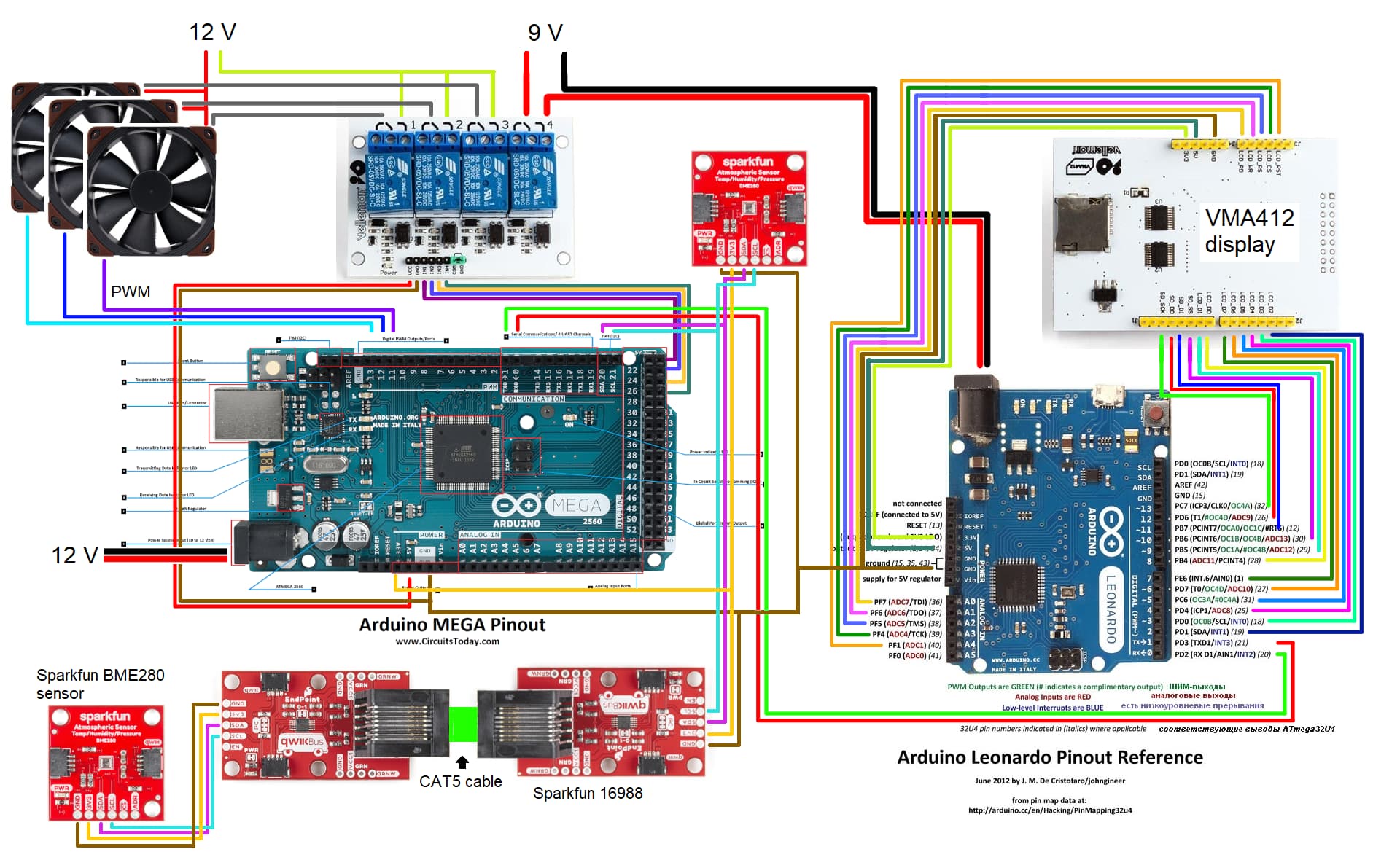
The right side is basicly a Leonardo with a display (shield).
The idea is that I would like to be able to use a button (not in the drawing present at the moment) to disconnect the Leonardo.
The Leonardo will only be used for display and occaisonally give some controle signals back to the Mega as feedback.
The Arduino on the left is a Mega and is attached to 2 BME280 sensors, one via 2 Sparkfun Endpoints with 3 meters CAT5 cable in between, attached to 3 fans via PWM and attached to a relaisboard.
The relais should control the power of the Leonardo and the fans, to power off in case they are not needed. But I wonder if just lowering the PWM signal isn't enough?

Why use a Leonardo in such a way? Because I noticed it hasn't enough space for some nice fonts and functional coding. So I bought the Mega, now I can split the task between them. Also, it would be nice to be able to turn off the display.
Hopefully, if everything goes well, I might add other functionality to the coding on the Mega.

I have multiple questions and i will probably be asked to post the code I already used, sooner then I am ready for.
So I hope we can start with this diagram.
I do not know what pull ups are, but before I figure out what those are, I really need someone to help me and point out that I actually need one and perhaps give a hint where I need one (or more).

The first question that inspired me to ask for help: can I connect 2 Arduinos via TX/RX and ground, if one of those Arduinos will be powered on and off independently from the other Arduino?
Because I read that you shouldn't put power on lines if the Arduino is off..
I'm sorry if this is a very simple question. But I'm really curious for the answer, since I only have basic knowledge of electronics.

Fritzing and tons of text.....
Please extract the essential facts. Your personal history makes the post less interesting to read.
What works and what doesn't work?
Always add only one new device at the time and verify its function. Then verify the next.

If You suspect an electrical issue You need to produce proper schematics. Pen and paper often works well. Reduce the multiple devices to one to limit the work. Split it to one drawing per controller and its peripherals.
Links to datasheets for peripherals, power supply, etc.., please.

1 Like

Thank you for your reply. You are absolutely right, I should work on that. I read the datasheets and I know why I want to connect certain ports, but, in my effort to keep it short, I did not mention it.

Please forget everything I posted before.
Maybe, for now, we can focus on my question (the last alinea of my post):

The first question that inspired me to ask for help: can I connect 2 Arduinos via TX/RX and ground, if one of those Arduinos will be powered on and off independently from the other Arduino?
Because I read that you shouldn't put power on lines if the Arduino is off..
I'm sorry if this is a very simple question. But I'm really curious for the answer, since I only have basic knowledge of electronics.

I like to thank you in advance,

First, the reason not to have power on the Arduino microcontroller pins when power is off is due to phantom-power which can cause all manner of bizarre happenings!
"Phantom Power" to Arduino via input pin??? - Using Arduino / Microcontrollers - Arduino Forum

Connecting 2 Arduinos via serial (Rx-->TX, Tx-->Rx) is often done. Beware EMF interference from AC florescent, motors, industrial equipment... Even lightning! Remember, long unshielded wiring is an antenna just waiting for a signal.

Now, for serial-serial, you can avoid phantom-power issues by using an opto-isolator to isolate the serial line . Optos will however limit the BAUD rate, testing required.

Reference:
image

Caveat:
The above cut 'n paste graphic from a stackexchange post should not be taken verbatim with respect to external resistor values. After a back-n-forth discussion with Paul_B, I strongly suggest that the datasheet for the opto-issolator selected be consulted and the collector load resistor be chosen based on the information presented.

Hi, @Marco_B
Can I suggest before you start your project, you write some codes just for each bit of hardware to prove your connections and basic hardware.

Also at this point it would be better if you got in the habit of drawing your schematics rather than cut/paste and mutli-colours.
An image of a hand drawn schematic will be fine, include ALL power supplies, component names and pin labels.

Thanks.. Tom.. :smiley: :+1: :coffee: :australia:

If you spend some time with KiCad which is free or the many other CAD packages available for free some being demo programs will make it a lot easier for you. If communications is critical take a hard look at CAN it is fault tolerant such if a node fails the rest keep on working. Frizzing is not very useful for troubleshooting or to anybody that is not familiar with the boards.

Could this (Pinouts | Adafruit ISO1540 Bidirectional I2C Isolator | Adafruit Learning System) be a alternative for an octocoupler for the connection between two Arduino's?

If not, might it be a temporary solution to power on both Arduinos if I need both and when I'm done, turn off the power, disconnect one of the Arduinos and power the other Arduino back on?

I am not familiar with that part but it appears it will do the I2C isolation you need.

First thing that stood out is that you power a four-relay board from the Mega. Can't do that.
Max current draw from a Mega with 12volt on the DC socket is about 100mA (one relay).
Two relays 'on' at the same time will overheat the 5volt regulator and reboot the Mega periodically.

Don't know the current draw of the display on the Leonardo, but the same thing applies there.

Why didn't you control the fans with logic level mosfets (no relay board).

Curious why you didn't use one processor (the Mega).
Piggy-backing two processors usually creates more problems than it solves.
Leo..

Hi,
You will find PWM controlling the fans the way you have them will not work, the fans controller and the Arduino PWM have to share a common gnd.
In your circuit they do not.
If you are going to use relays to isolate the fans, then high side switch the power, not low side as you have it.
Low side leads to phantom powering in the signal wire, thus consuming current from the Arduino when the power is switched off.

Tom.. :smiley: :+1: :coffee: :australia:

This topic was automatically closed 180 days after the last reply. New replies are no longer allowed.