Hello there,
this is my first post and if anything is missing or if there are some standard things which I am not following just shoot me a quick info on that and I'll try to fix it asap
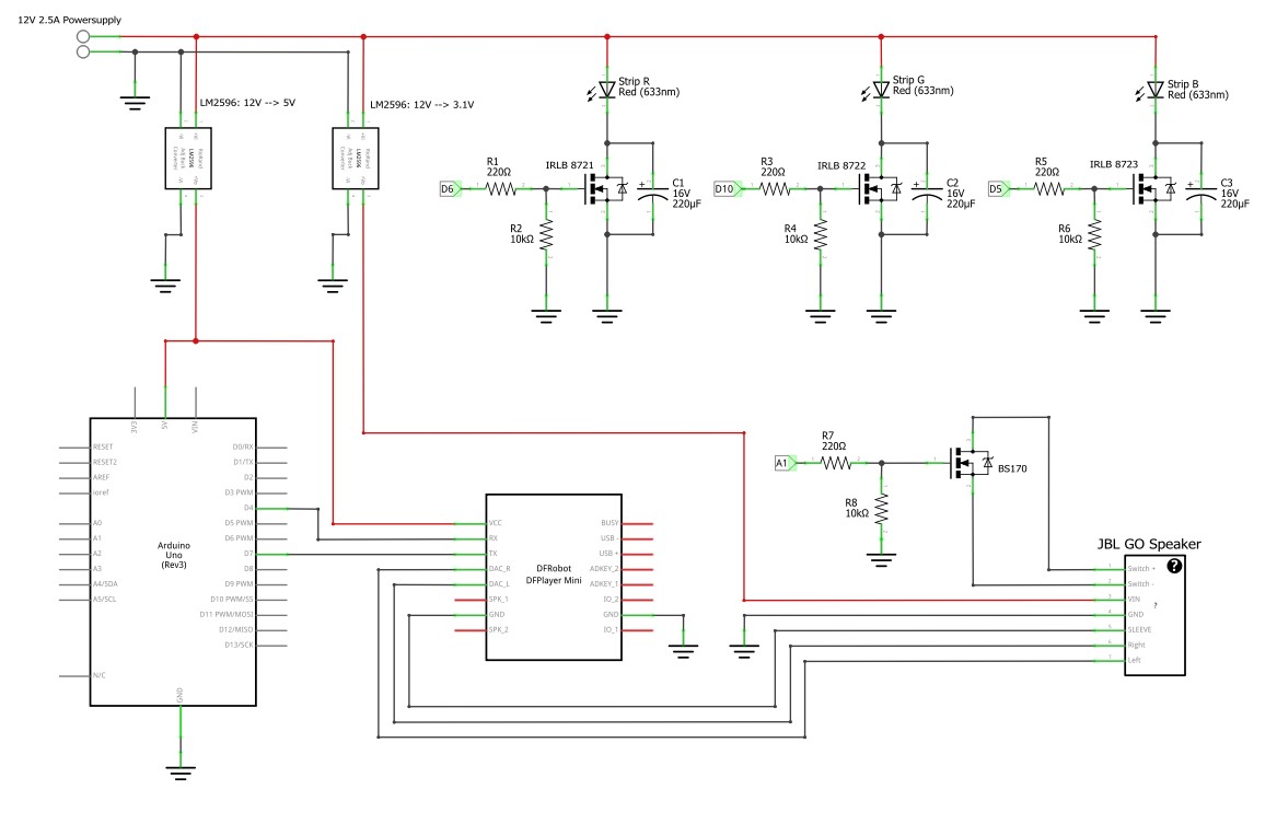
I have modified a construction warning light to include a short bit of RGB Ledstrip and a speaker to play some sounds. Parts used:
Arduino Uno Rev. 3
DFPlayer Mini
NRF24L01 (not included in schematic for better overview, but directly wired to Arduino)
"Hijacked" JBL Go Speaker (removed battery and supplied with ~3.1V, removed automatic shutdown, power button wired to BS170 NMos for toggling on by Arduino)
2x LM2596 to to convert from 12V supply voltage to 6V and 3.1V
70cm LED Strips (12V, not in excess of 140 mA per Color)
IRLB8721 NMos for the LEDs
BS170 NMos for toggling the Speaker
Problem:
When the LEDs are toggled on fully, either via digitalWrite(pin, HIGH) or analogWrite(pin, 255)), the LEDs light up and there is no humming on the speaker.
When the LEDs are dimmed via PWM the speaker starts to hum. I am clearly able to hear the difference in frequency when Red (Pin 6) and Blue(Pin 5) are dimmed in comparison to Green (Pin 10). I think the reason here is the difference in the PWM frequency by the Arduino on Pin 5 and 6 (980 Hz) and Pin 10 (490 Hz).
The humming is clearly audible even when no sound is played by the DFPlayer.
When GND oder VIN on the DFPlayer are disconnected the humming stops.
When the RX or TX line on DFPlayer are disconnected the humming is still present.
I have tried to use some capacitors with varying size connected from Vcc 12V to GND but without success.
I think that the humming could come from small voltage drops on the 12V Rail because of the fast switching which the power supply can't compensate but this is just a guess and I have no oscilloscope at hand to check this in detail.
I would appreciate an idea how to suppress the humming, maybe by including some capacitors to either stabilize the supply voltage or the filter out the frequencies.
You are really running your UNO Vin on 6V? That's too low. With your voltage converter, you could better step down to 5V and apply that directly to the UNO 5V pin.
I see that there are no bypass capacitors on the 12V supply. That would be a great place to start. So, between ground and +12V especially physically near the LED MOSFETs.
The noise can follow other paths, such as ground. So if bypassing the 12V doesn't help, you should post complete photos of your entire wiring system.
The 6V are needed to supply another LED Module which only runs on 6V and right now I do not have another step down module at hand .
Do you have a quick hint how large the bypass capacitors should be?
Then I'll quickly check, whether including them helps to fix the problem, otherwise I'll try to take some pictues.
The 6V are needed to supply another LED Module which only runs on 6V and right now I do not have another step down module at hand.
That's not shown on your schematic, looks to me like it only supplies the Uno.
Lots of scope in that circuit for noise if the wiring isn't properly routed, which is why we need photos.
What capacitors do you have? Exact values are not critical, if you have some anything between 100μF and a few thousand then putting them across the supply close to each device will help.
I've only used a DF Mini once and found I had problems unless I put a 1000μF or bigger across its power pins.
viermusketiere:
The 6V are needed to supply another LED Module which only runs on 6V ......
It definitely is beneficial to know what the recommended supply voltage is .... or what the recommended supply voltage range is. Not just for arduino ..... but for anything.
aarg:
You are really running your UNO Vin on 6V? That's too low. With your voltage converter, you could better step down to 5V and apply that directly to the UNO 5V pin.
I see that there are no bypass capacitors on the 12V supply. That would be a great place to start. So, between ground and +12V especially physically near the LED MOSFETs.
The noise can follow other paths, such as ground. So if bypassing the 12V doesn't help, you should post complete photos of your entire wiring system.
I have changed to 5V step down and connected it to the 5V Arduino Pin, the other module still works with 5V instead of 6V.
Southpark:
It definitely is beneficial to know what the recommended supply voltage is .... or what the recommended supply voltage range is. Not just for arduino ..... but for anything.
I totally agree and admit that I have just not read the datasheet for the Arduino properly
PerryBebbington:
That's not shown on your schematic, looks to me like it only supplies the Uno.
Lots of scope in that circuit for noise if the wiring isn't properly routed, which is why we need photos.
What capacitors do you have? Exact values are not critical, if you have some anything between 100μF and a few thousand then putting them across the supply close to each device will help.
I've only used a DF Mini once and found I had problems unless I put a 1000μF or bigger across its power pins.
I only have a few capacitors some 0,1uF (Ceramic) ones and a few electrolytic ones ranging from 1uF to 470uF. I have just thought about trying to place some of my bigger ones (470 + 220 + 3x 100 uF) in parallel and wire them across the power pins of the DF Mini.
Will report back with the results in a few minutes.
I can only archive around 400uF in total, when I wire them in parallel. I'll try and see whether I can find some other caps in the house.
I attached some pictures of the wiring which is quite confusing because I have already mounted everything inside the base, when I found about about the humming.
My initial thoughts on seeing them was "yes, that's going to hum".
Rule of thumb "if it looks untidy then there will be problems".
I have just thought about trying to place some of my bigger ones (470 + 220 + 3x 100 uF) in parallel and wire them across the power pins of the DF Mini.
Just put the 470μF across, like I said, exact values are not important.
I don't know where to start
The first thing is that the ground to the audio circuits and the power to the everything else, most especially the LEDs (because of their high current consumption), should be made with different wires and be joined at one common point. I can't tell from the photos how the grounds are routed, but I am guessing the return path for the LEDs is at some point shared with the audio return path. Trace the current path for each, they should not share the same wire at any point. They have to meet somewhere, but not flow through the same wires before they meet.
A Uno is great for developing ideas and experimenting, but something like a Nano Every is far better for building into a finished project.
Just noticed, this is not the cause of your problem but R2, R4 and R6 are in the wrong place, they should be connected to the output pin, not the MOSFET gate, so the opposite end of R1, R3 and R5 to what they are now. As you have them they form a voltage divider with R1, R3 and R5, which is not what you need.
PerryBebbington:
Just noticed, this is not the cause of your problem but R2, R4 and R6 are in the wrong place, they should be connected to the output pin, not the MOSFET gate, so the opposite end of R1, R3 and R5 to what they are now. As you have them they form a voltage divider with R1, R3 and R5, which is not what you need.
Noted that already but because of time reasons I wont change that, unless there are other reasons pointed out which would need me to dismantle and work on the PCB.
PerryBebbington:
Thanks for the photos.
My initial thoughts on seeing them was "yes, that's going to hum".
Rule of thumb "if it looks untidy then there will be problems".
Just put the 470μF across, like I said, exact values are not important.
I don't know where to start
The first thing is that the ground to the audio circuits and the power to the everything else, most especially the LEDs (because of their high current consumption), should be made with different wires and be joined at one common point. I can't tell from the photos how the grounds are routed, but I am guessing the return path for the LEDs is at some point shared with the audio return path. Trace the current path for each, they should not share the same wire at any point. They have to meet somewhere, but not flow through the same wires before they meet.
A Uno is great for developing ideas and experimenting, but something like a Nano Every is far better for building into a finished project.
I'll now reroute the wires and try to sperate them and create one single, central point where they meet (12V in and ground) in close proximity to my inputjack.
I'll have to check with something lower than 470µF, because of the voltage ratings of my capacitors available.
I'll have to check with something lower than 470µF, because of the voltage ratings of my capacitors available.
Whatever you have. If what you have doesn't help then a bigger capacitor won't make any difference. There are 2 things here:
Sources of noise, and the source I am concerned the most about is from current to the LEDs sharing the same wires* as the audio signal.
Suppressing the noise once there is noise, which is what the capacitors help with, but better not to have noise in the first place.
Never forget that wires have resistance and resistance results in voltage across the ends of the wires when you pass current through them. In the case of your LEDs you are chopping up the current with PWM, meaning the wires carrying that current will have a rapidly varying voltage across them, which shows up as noise in the audio circuits if you are not careful.
Quick Update:
When I add an Capacitor to the Power Pins of the DF Mini there is no audible effect in volume or frequency, so I think this solution wont work.
I'm in the progress of rewiring my everything to one common point (12V and GND) but I think this will not have the effect of removing the hum.
I scrolled back thru the thread and re-read the part about a bypass capacitor close to the Mosfet and just attached a Capacitor (220µF + 100µF) directly from drain to source and the hum went away. I noticed that the LEDs got a little brighter aswell while the Capacitor was attached.
Changing the wiring in the way suggested is going to help too.
Within reason there's no such thing as too much capacitance across the supply. Put the capacitors as close to each device as possible, in effect they supply the instantaneous current used by the device.
Changing the wiring in the way suggested is going to help too.
That's definitely happening right now.
Okay, but just to make sure: It's not bad that the capacitor is not directly across the supply but wired directly from drain to source of the mosfet? (See attached and updated schematic)
The capacitors do not go across the MOSFET, that would probably fry them.
Docoupling capacitors go across the supply, from your +12V rail to ground, close
to the MOSFETs that are switching.
viermusketiere:
Do you have a quick hint how large the bypass capacitors should be?
Large. Start at 1000µF and work up perhaps? Even small voltage interference
will be easy to hear in the audio as the ear is really good at detecting small signals.