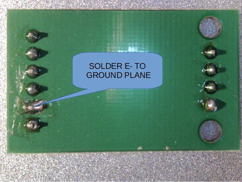
I received some HX711 MH boards from China that seems to have a PCB design error as GND and E- are not connected to each other. The solution is simple, the whole back plane of the board is GND so remove some solder mask around the E- pin and apply enough solder to make a connection to GND.
Background:
I ordered the XFW-002 type and I received the MH type of board. The obvious difference is the lack of rate selection jumpers so I had to test to see if this board was running at 10 SPS or 80 SPS. Normally the E- connection and the GND connection are tied together with this chip and when I measured the resistance between the RATE pin and E- there was no connection, however the RATE pin was connected to the GND connection. Weird. So I tested the board with a scale and it was running normally at around 10 samples per second. The voltage between GND and E- was about 0.8V and there were spurious spikes in the data transmission line of the chip. The spikes are too short to be picked up by the Arduino. When I connected E- to GND the spikes were gone. The shielded HX711 MS V1.2 board I have got the E- and GND connected and the XFW-002 also got the E- and GND connected according to the pictures. In the documentation the GND and E- are also connected. It seems that the current from the load cell finds it’s way to ground through a protection diode in the chip.
For those interested I made a non blocking library for this chip.