I need 2 SPI, is it possible with arduino?

Hi everyone,

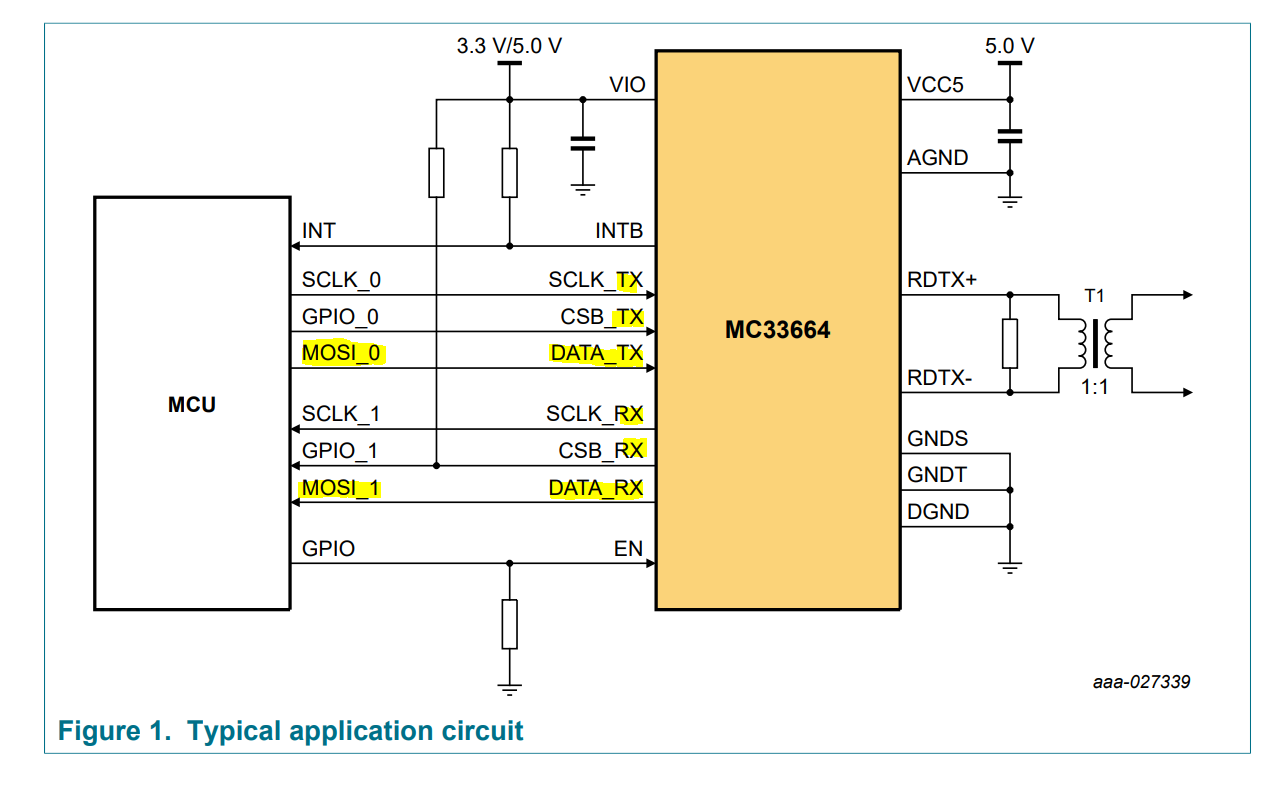
In order to use the NXP MC33664 componant, I need 2 SPI.
One SPI is configured as a master in order to send a message to the MC33664 and another SPI is configured as a slave in order to recieved the response. I know is weird but this componant work in this way.

Currently I anderstand that Arduino has only one SPI, right ? Is there a way to add another SPI GPIO ?

Welcome to the forum

SPI is a bus protocol so you can connect multiple devices to the same bus and control which of them is used at any time by means of their individual SS pins. MISO, MOSI, and CLK are common between all devices

Thanks for you response.

Unfortunately is not so easy with the componant MC33664.
One MC33664 need two different SPI to work
That why I ask if there a way to have two different SPI with one arduino

And the Arduino you have is ?

I looked at the datasheet and I do not see anything like that the chip needs a two SPI .
Any SPI works this way - first a request is sent, then a response is received. This does not require two separate SPI buses.

There are a lot of arduino compatible chips that has more than one SPI bus on board - Arduino Due, most of STM32s, RP2040, lot of Teensy....
But I still in doubt that you need this

+ESP32.....

Thanks for you help !

@b707 about the MC33664, please read more about this componant, I confirm it need 2 different SPI to work :wink:

@srnet currently I don't have any Arduino

ok, so read the post #6

Thanks a lot for your help again,

About arduino DUE, you mean I can use those 2 SPI, right ?

nope
It is not two SPI ports, the upper is ICSP header for USB-UART chip Atmega16u2

I don't know very well how to use two SPIs on a Due, but this headers definitely is not what you need.
Better take a board, that supports using multiple SPIs in Arduino sketches, for example STM32 bluepill, ESP32 or rp2040

Ok perfect I will check these boards, thanks !

Currently I found an Arduino uno and a raspberry, I imagined to use the raspberry as a master connect to the MC33664 and the arduino as a slave connect to the MC33664, but I'm not sure it could work...

I think I should use one of boards you propose, but in anyway, the program to make seems complex to perform

I work a lot with STM32 and could help you, but without a chip on hand, it's difficult.

If you end up using an ESP-32, this example has helped me;

What is your use of this module specifically? Is it just used for communicating between multiple MCU's?

The MC33664 is using to communicate with several MC33771 (this one is using to work cells batteries) with TPL.

everything is well explained here https://iisb-foxbms.iisb.fraunhofer.de/foxbms/gen2/docs/html/v1.1.1/software/modules/driver/mic/nxp/mc33775a.html

What about configured one of one SPI of STM32 bluepill (or ESP32) in slave mode and the other one in master ?

Hi everyone,

I finally order an ESP32 and for now I try to prepqre the code.
I' m using the example given by GigaNerdTheReckoning
https://github.com/espressif/arduino-esp32/blob/master/libraries/SPI/examples/SPI_Multiple_Buses/SPI_Multiple_Buses.ino

It seems of and easy to send data but what about configured the ESP in SPI Slave to read message from a master ? Could someone help me please ?

Hi everyone,

I have an ESP32 board. In order to use component MC33772 and MC33664 I have to use 2 different SPI:

It's explained in the datasheet:

  • In order to send a message, use SPI1
    MCU(Master) ---> MC33664 ---> MC33772(slave)
  • In order to receive a message (the response), use SPI2
    MCU(Slave) <-- MC33664 <-- MC33772(Master)

I try to use the example "master_slave_polling" from ESP32 lib, but it doesn't work for me.
So I would like to start from the beginning with you and hope someone could help me to complet the code.

Currently I have

void setup() {
  // SPI Master
    // VSPI = CS: 5, CLK: 18, MOSI: 23, MISO: 19
    pinMode(VSPI_SS, OUTPUT);
    digitalWrite(VSPI_SS, HIGH);
    master.begin();

    // SPI Slave
    // HSPI = CS: 15, CLK: 14, MOSI: 13, MISO: 12
    slave.setDataMode(SPI_MODE3);
    slave.begin(HSPI);
}

void loop() {
 
  master.beginTransaction(SPISettings(2000000, MSBFIRST, SPI_MODE3));
  gitalWrite(VSPI_SS, LOW);
  master.transferBytes(MyMessage, MSGLEN);        
  digitalWrite(VSPI_SS, HIGH);
  master.endTransaction();
}


and I would like to send
MyMessage: 7F 15 3B 01

and finally, I would like to read the message incoming in MOSI GPIO 13

Thanks a lot for yourhelp !

Topics merged

No one can help ?

Your questions are not clear.
You don't explain what's mean 'it doesn't work".
Please provide complete code and explanation< how it should work and how it works in reality