I have a circuit in which the highest frequency of interest is 200Hz, I want to be able to sample this signal at 500Hz (obeying the Nyquist rule) and then analyse the signal data in Matlab.
Currently when I am using analogRead to convert to digital, the complete loop in taking around 5-6ms to run without any delay so I have a slow ADC. I have measured this by writing to an led and measuring the time between it is on (start of loop) and off (at the end of the loop).
I am using an Arduino Due since I can set the analogReadResolution to 12 bits. How can I set the sampling rate to 500Hz so that each loop runs accurately at 2ms?
Code is displayed below for more understanding. It's a fairly simple code as I'm not proficient with Arduino and I only need to use it for sampling and digitisation of my signal.
const int analogInPin = A0;   // analog input pin that feeds in from circuit
const int threshold = 3500;   // a threshold level that's in the range of the analog input
const int ledPin = 13;        // pin that the LED is attached to
signed int sensorValue = 0; // value read in after A-D Conversion
float voltage = 0;

// the setup routine runs once when you press reset:
void setup() {
  // initialize the LED pin as an output:
  pinMode(ledPin, OUTPUT);
  // initialize serial communication at 9600 bits per second:
  Serial.begin(9600);
  // changes resolution from default to 12 bits
  analogReadResolution(12);
}

// the loop routine runs over and over again forever:
void loop() {
  digitalWrite(3, HIGH);
  // read the input on analog pin 0:
  sensorValue = analogRead(analogInPin);
  // Convert the analog reading (which goes from 0 - 4095) to a voltage (0 - 3.3V):
   voltage = sensorValue * (3.3 / 4095.0);

// if value returned by ADC is greater that threshold
// then set the value to 0 and flash LED
  if (sensorValue > threshold) {
    sensorValue = 0;
    voltage = 0;
    digitalWrite(ledPin, HIGH);
  } else {
    digitalWrite(ledPin, LOW);
  }

  Serial.println(voltage);

  digitalWrite(3, LOW);
  delay(1);
}
Serial functions are slow, capture measurements into an array and write out after measurement completed.
Don't do measurement scaling (float is slow) during the measurements, you can do afterwards.
I was able to do 32 analog reads every 3 Arduino Due clock cycles (3*11.9ns = 35.7ns, 28Msps): https://forum.arduino.cc/index.php?topic=417851.msg2883182#msg2883182
Without delay, Serial and with array you will be able to measure much faster than with 200 samples per second. Only if its too fast, add delayMicroiseconds() calls into the game. The loop() function has some overhead, so you may want to do the measurements in your own for(i=0; i<N; ++i) {...} loop in setup() yourself.
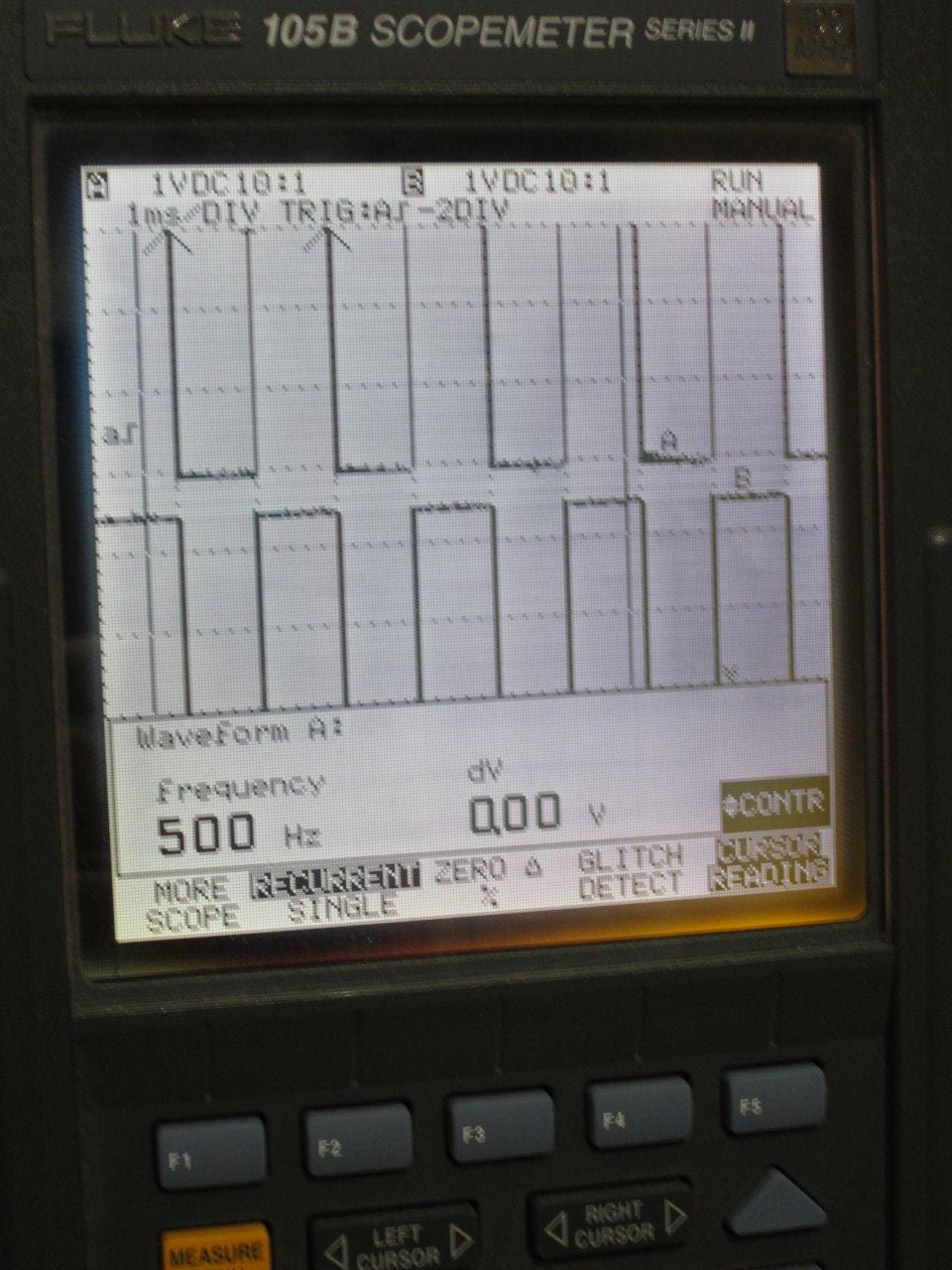
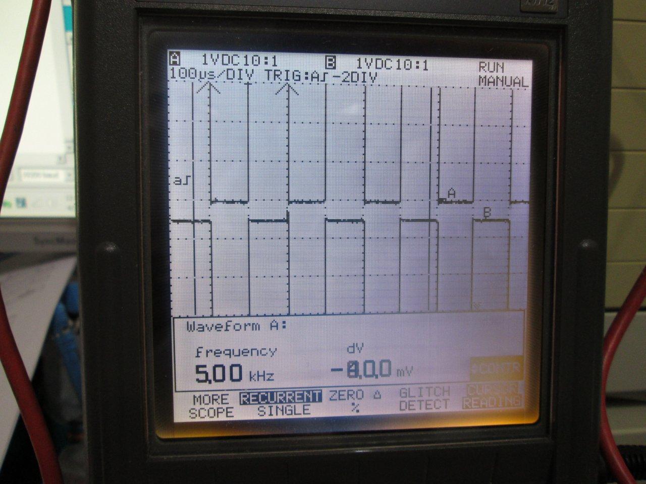
Here's a prog I just finished that generates a PWM signal with adjustable duty cycle, has a separate digital output track the PWM, and triggers an analog sample each cycle. the loop() code only has two lines, setting the PWM duty cycle, and printing the analog input, everything else is in hardware. The areas not addressed in the program are data buffering and reading multiple A/D channels. The basic setup is a 100K pot between 3.3V and GND feeding into A0. The main PWM output is D2 (the top trace on the scope), the tracking waveform is on D13 (flashing the led). The TX and RX LEDs show error codes (that set and clear in the first few cycles). My A/D resolution is set at 12 bit, but with noise (I'm still tracing down) you effectively get 9/10 bit resolution. The sampling appear to working at 5kHz. The attachments show the setup and the two scope screen captures.
PS I had to add the code as an attachment as all the commenting puts me over the text size limit...
I just ran a test adding a timestamp to the analog output value. The source for the timestamp is the PWM timer counter. As the counter wraps each cycle you should see the same time each sample. I set fixed the duty cycle @50% (as opposed to using the pot setting). The cycle times are dead on up until ~13 kHz where you start to see some jitter. At 20kHz, the RMS timing jitter is about .4 microseconds. I would need to setup/sync a second timer counter to get absolute timings.
xuthus - thank you for your comment. That is a very long code but with the excellent comments it becomes much more readable. How did calculate your sampling frequency to be 5Hz and how did come to the conclusion that the resolution is 9/10 bits?
ard_newbie - thank you for your reply. Can I use a baud rate of 115200 or 230400? Since I am using coolterm to capture the data to a text file the highest baud rate is 230400 and will modifying the baud rate maintain the sampling at 500Hz?
The sampling frequency for the timer counter is defined by (Timer Clock Source)/REG_TC0_RC0. The timer clock source is set at MCLK/2 (42 MHz) and REG_TC0_RC0 is set at 8400000. In the program REG_TC0_RC0 stays fixed, I change it and recompile each time. WRT the 9/10 bit resolution, I was took the serial output of analogvalue, cut and paste into excel and did the analysis. Assuming gaussian distribution of noise (first pass), the RMS jitter is simply the standard deviation of the samples, which turned out to be ~3.5. If you watch the binary value of analogvalue (while not making any adjustments) you can see the first 9-10 bit are pretty stable. Having said that, I have traced down one (of many) source of noise. the analog input reads the pot wiper with the pot connected between +3.3V and GND both taken from the DUE. Now if you put decoupling caps (100pF) across +3.3 and GND at the pot and across the wiper and GND, the RMS Jitter went from ~3.5 to ~1.1. The next thing to look at is the ADREF voltage.
ard_newbie: Its running 500Hz (2 mS) with the USB Native port at 230,400 (using IDE serial monitor). The RMS timing jitter for the samples comes out ~.27 microseconds.
I first tried the programming port at 115,200 with no problem. Then I added the native USB port (with second cable to the computer) for giggles and grins. As for the timing jitter, I enabled timestamping of samples and collected ~27000 samples from the native port at 230,400. I cut and pasted the samples into excel, separated the timestamp from the data, and ran a standard deviation on all the samples. Assuming a gaussian distribution of noise (first pass), the RMS jitter is equal to the standard deviation of the data set. The timestamp (and standard deviation) is in clock counts which you then convert to time knowing the clock frequency (42 mHz).
Did you try 230,400 with the programming port, is there any difference? Whats the difference between the programming port and the native port? How do you enable time stamping on samples and how do you manage to precisely calculate a number of samples?
ard_newbie - Some comments I have from your code, I would be grateful if you could answer them.
what is meant by '#define Serial SerialUSB'?
Is there a way you used to measure the sampling frequency ( i.e. to confirm it was 500Hz)?
Also did you use the programming port or the native port?
LED_BUILTIN is declared but not used, is there a reason for this?
Also as above, do you thing it would be okay to use 230400 as the baud rate instead of 250000?
I just checked, 115200 is the highest rate the programming port supports. The programming port goed thru the 16u2 chip and has additional functionality (auto-reset/auto-hang). As for the timestamping, I've attached the most recent update to the sketch which has the timestamping code. Timestamping is enabled/disabled by commenting out the appropriate analogvalue assignment line in the ADC_Handler module. As for collection of samples, I let the system run for a bit, turned off auto-scroll, select the data, and cut and paste. I am not looking for an exact number of samples just a large block of them (my old copy of excel only allows graphing 32000 samples).
I've made some useful changes to the program. It now samples and processes two analog input channels. I've fixed the PWM at 50%. It uses channels AD7 and AD6 (Pins AD0 and AD1 respectively). I've packed the two sets of readings into a 32-bit output as follows: