Hi, I need help. I can't get any reception from my radio.
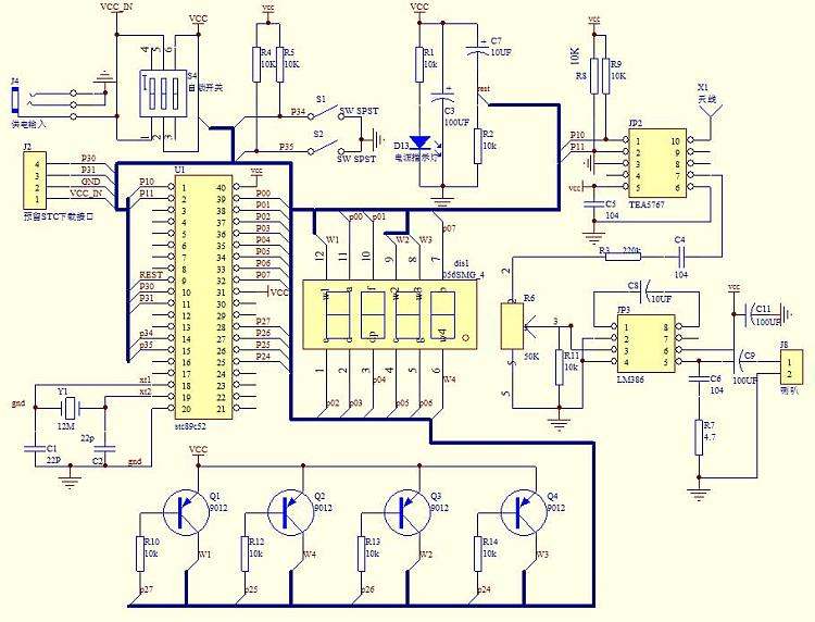
I've purchased a DIY radio kit online and it uses a TEA5767 chip, a STC89C52 microcontroller, and an LM386 amplifier. I assembled everything correctly but I can't seem to get any reception from it. I scanned every station and all I here is humming (which is normal for this kit) but it must also hear the station after.
I've done a lot of research, including the pins of the microcontroller and the receiver chip. Someone said on youtube that this situation needs checking the connection somewhere between the TEA5767 chop and the microcontroller, or between the TEA5767 chip and amplifier. But I triple checked it including the components and their polarity.
And also, he said that some PCB design of this product lacked one connection, so maybe that is what I am missing.
Do you understand the schematic ? Every wire and connection ?
Now, trace through with a decent multimeter or oscilloscope, and verify the major voltages and signals.
I hope you managed to flash the program into the cpu before testing ?
Thank you for replying, I don't have an oscilloscope but I have a multimeter. I already checked every connection and everything is correctly connected based on the PCB and schematic.
Unfortunately, my PCB was only one sided, so I improvised and used the top layer of the original PCB as the bottom layer of my PCB, and then soldered the remaining connection (the connections for the other layer of the original PCB) using jumper wires. The results are not eye-pleasing but I checked every connection and its all correct. I'm very sorry, I can't provide you a picture. Everything at the back is very messy.
I'm sorry, what I mean by connected is I checked everything using continuity. The only voltages I checked were the supply and the vcc pin of TEA5767. I'll update after I've checked everything again. thank you.
I already see a difference between your board and the picture of the original board. At the bottom of the original there is a stack of three resistors, all close together. Then a row of 4 holes above them. Your board has no row of holes and your resistors show a space between two of those resistors. NOT the same board layout as the original. Wonder what other minor changes were made?
The original board obviously has plated through holes for the component leads. Your board does not have those, which makes it so very easy to have a hidden cold solder joint. Good luck!