I have spent time reading what I can find on this topic and have come up with a solution which I would like to have sanity checked by the experts here before proceeding....
I am using the 3.3V inputs on an ESP8266 to detect switches which drain to ground.
The inputs are pulled high using the internal pullup resistors.
The environment is however prone to accidental connections of stray voltages to the switched line. I therefore wish to protect the ESP8266 from stray external voltages. I did consider using optocouplers but the ESP8266 and the rest of the system all share a common ground.
I understand that the ESP8266 has internal diodes to protect against ESD, but I suspect I need more robust protection against longer duration stray voltages.
I read that Shottkey diodes with a lower forward voltage of 0.3V would be better than silicon diodes.
Additional information
The environment is a a 3-rail model train layout. Sections of the running rail are isolated from the rest of the rail and connect to my input sensor. When a train passes onto the track, the axles connect the isolated rail to the other rail, thus grounding it. This grounding is what I am using to detect the presence of the trains.
The source of the stray currents could be:
A short between the center rail which carries a 18V digital AC-like current (caused by a derailment)
12 V from an accessory (unlikely)
16 V AC from another accessory circuit (unlikely)
Electrostatic discharge from someone touching the isolated track
DaleSchultz:
I therefore wish to protect the ESP8266 from stray external voltages. I did consider using optocouplers but the ESP8266 and the rest of the system all share a common ground.
That is no reason why an optocoupler would not provide excellent and indeed, total protection. In particular, you mount it adjacent to the microcontroller module and wire its ground to that module (i.e., it connects from the pin to ground and uses the internal pullup). The LED side you take both wires together away from the module, to the part of the circuit (with a series resistor) which you wish to sense. This provides maximum isolation even if there is some connection of the microcontroller module's ground to the rest of the circuit. You would want to protect the optocoupler LED from reverse voltage by a parallel diode.
For your circuit as given, R1 and R2 could both be 4k7. A 10 Ohm value for R2 would burn if the track conveyed a negative 12 V to it.
You might put 8 1A power diodes in series to connect between the board 5v bus and ground. If the 5v bus voltage gets up to 5.6v, the diodes should start bleeding off any excess voltage.
Make sure R1 and R2 are small enough to allow for a proper LOW signal. Together no more than 5-10k or so, as they're forming a voltage divider with the internal pull-up. If you want those to be larger in value, you have to use an appropriate external pull-up.
Values as given in your circuit qualify, but I'd want R1 to be much larger in value, as it's the current limiting resistor for when your voltage goes negative - you mention 18V AC, so that could be -25V or so! After deduction of the forward voltage of the diodes that's 24V over the 10Ω resistor - that gives a current of 2.4A. That's going to mess up things badly, starting with your power rails. That resistor should be increased, 1k would be a safe minimum, resulting in a current of 24 mA.
So here is what I was thinking originally with the optocoupler approach:
I have added in a string of 1N4001 diodes as suggested by zoomkat - a great idea, I will do the same to my 12V bus with 17 of them.
As for protecting the optocoupler LEDs, I have shown a parallel diode D1b but I was thinking that it should bridge the resistor as well, and then I thought, why not add the diode so that no current can go towards the +5 V bus? - as I have depicted as D1a. D1a and D1b being alternatives.
If I go the non-optocoupler route, yes I agree R2 should be more like 1k.
Additional information:
Apart from the diode string limiting the 5V bus to 5.6V, the circuit will be repeated 8x per ESP8266 module and there will be multiple such clusters long the 5V bus. Each ESP will serve 8 sensors and I will have about 7 such sets of 8. The 5V supply is coming from an old PC power supply (which also supplies my 12V DC bus).
zoomkat:
You might put 8 1A power diodes in series to connect between the board 5v bus and ground. If the 5v bus voltage gets up to 5.6v, the diodes should start bleeding off any excess voltage.
I put my meter across the lines and turned the voltage up on the power supply watching the voltage.
I got to 5V and went past 5.6V and on up to 7V! The diodes were getting hot so I stopped.
I suspect my bench power supply just keeps adding more current as they conduct. (I think it can supply 1.5A)
Am I correct in thinking that this series of diodes would only help with short duration stray currents and only if the stray current has less than 1 Amp available?
I have a 4A fuse on the power supply on the layout.
Granted, I could use diodes rated more than 1A.
Certainly the digital stray current that could arrive should shut off very fast if it detects a short to ground.
My 16VAC circuit has a 3A fuse, not sure if my 12V bus even has a fuse, I should add one!
DaleSchultz:
As for protecting the optocoupler LEDs, I have shown a parallel diode D1b but I was thinking that it should bridge the resistor as well, and then I thought, why not add the diode so that no current can go towards the +5 V bus? - as I have depicted as D1a. D1a and D1b being alternatives.
And indeed they are. I tend to favour the parallel approach as it positively ensures that no negative voltage (more than 0.7 V) will appear across the optocoupler LED. While there should be no reverse leakage through the diode if in series, the parallel version just looks nicer, Of course, that means the resistor absorbs that current if reverse voltage occurs but it will be in any case rated to the usual forward voltage (and to pass about 3 mA) so that is of no concern.
The whole idea of using the optocoupler is to isolate the train running voltages from the logic voltage, so the supply to the input of the optocoupler comes from the 12 V that is running the rails, not the 5 V. About 3 mA at 12 V - a 4k7 resistor. Dissipation 30 mW - trivial.
DaleSchultz:
If I go the non-optocoupler route, yes I agree R2 should be more like 1k.
I suggested 4k7 for R1 and R2, so 2k2 sounds nice.
Putting a shunt "pseudo-Zener" across the 5 V - or the 12 V - is a really bad idea if you are using a PC power supply (or indeed, most other sorts). The proper resistor values specified in the non-isolated configuration (not to mention D2) will prevent any meaningful current fed to the 5 V supply. This is a non-problem.
The trains are run using the square wave digital signal, and the track detection is grounding only, i.e. switching one rail to common ground.
I could use the 12V DC but since the 12V and 5V are both coming from the same PC power supply would I be achieving any additional separation using the 12V?
It occurs to me that the since the stray current may get to -24V, the resistor for the optocoupler may need to be calculated for 20.3 V (24 -5 -0.7) in order to protect the optocoupler... so I have mentally moved from protecting the ESP8266 from stray current, to protecting the optocoupler from stray current!
I am therefore now leaning towards the Schottky diodes solution again. It does mean 5 components per sensor rather than 3, but they may be cheaper than the optocouplers.
In fact I am now thinking that D1 may be able to be shared by all the sensors, making it 4 components per line.
You might look for some small/large 5.1v Zener diodes to limit a voltage spike. They do require a small amount of current flow before they start regulating, but might prevent a catastrophic board failure.
So I think I am nearing the final solution, thanks to the help from you guys....
I have now drawn the circuit that I will start testing showing 4 sensor lines. (I plan on doing eight)
+5V is actually +5.1 V coming from a PC power supply
C1 0.01uF
D1 1N5817
D2 1N5817
R1 2k Ohm
R2 2K Ohm
T1 through T4 = isolated train tracks (that get connected to GND when a train is present)
I think I will discuss a power line bus treatment using a Zener in another thread. For now lets assume the +5 line is good.
For testing I used 1N4001 silicon diodes. After testing sensors with the ESP8266, I substituted a simple sacrificial LED and resistor for the ESP8266 for stray current tests.
I applied the 18V square wave current to the Track sensor wire and there was insufficient reverse current to pop the LED! So I take that to indicate that it works as designed!
When my Schottky diodes arrive I can test with the ESP8266 again.
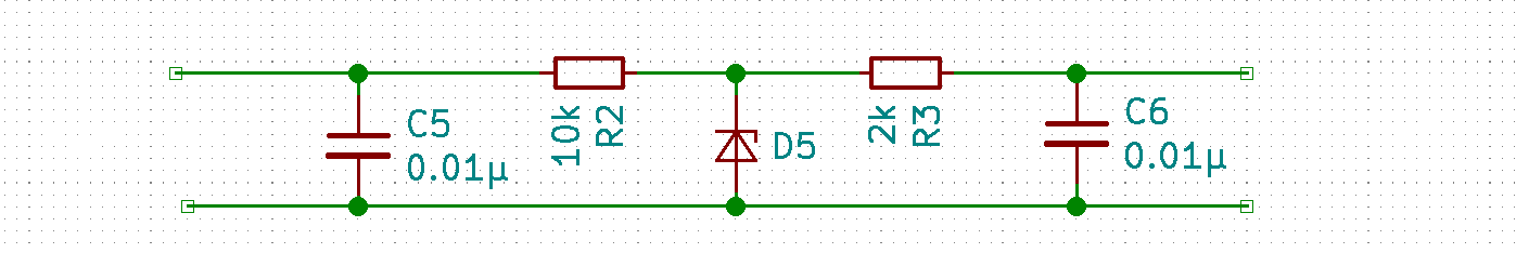
For automotive we used the attached ckt. And I agree an opto isolator would work as well.
I believe a key characteristic is the physical layout.
C5 should be right were the wire enters and directly to a ground plane, the remainder should be close to the ESP ground to minimize path length.
I don't know if you are making a PCB or using a general use board whatever you choose you should have an area for ground that can be used to terminate C5.
Also note, if you use an opto you must keep the inputs and outputs physically separate else esd will go right through the opto (been there done that).
BTW the ESP is not ESD protected by the diodes. They are what I would call "general protection". If you walk across your rug and discharge to the ESP input I believe it will damage the device.
John
D5 is a 5v transzorb or TVS ( i've not seen them lower than 5V)
you show a second capacitor, C5, which I do not have at all.....
I will probably construct these by hand on through-hole circuit boards, but have not yet laid out an exact plan. I will keep them as close as possible to the ESP pin.
I have an ESP8266 controlling our bedroom light and fan and I have had static discharges at least 3 times when pressing one of its buttons, and they have crashed the processor. A power cycle reset has brought it back to life every time (so far!)
you show a second capacitor, C5, which I do not have at all.....
This capacitor is your first line of defense against fast voltage spikes. In general you want to stop any unwanted perturbations before they get on the board when they can possibly couple to other signals.
If you go this route, I am rethinking the TVS location. It to should be near the input wire.