@ GolamMostafa
the purpose of the code is simply described in post #7.
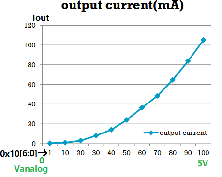
After executing the code in post #3, when I adjust the analog voltage on A0 of UNO, the dimming level is communicated to iW3690 via I2C, actually is the output level register 0x10 of iw3690 is written the updated value. Afterwards iw3690 controls the ON time of MOSFET Q1 in line with the targeted dimming level, thus LED current is dimmed/adjusted. below dimming curve is an example.
You can adjust the dimming of your LEDs/Lights by a wall mounted Dimmer; why are using the IW3690 Power Controller in parallel with Dimmer to regulate LED current/power?
@ GolamMostafa, Merry Christmas.
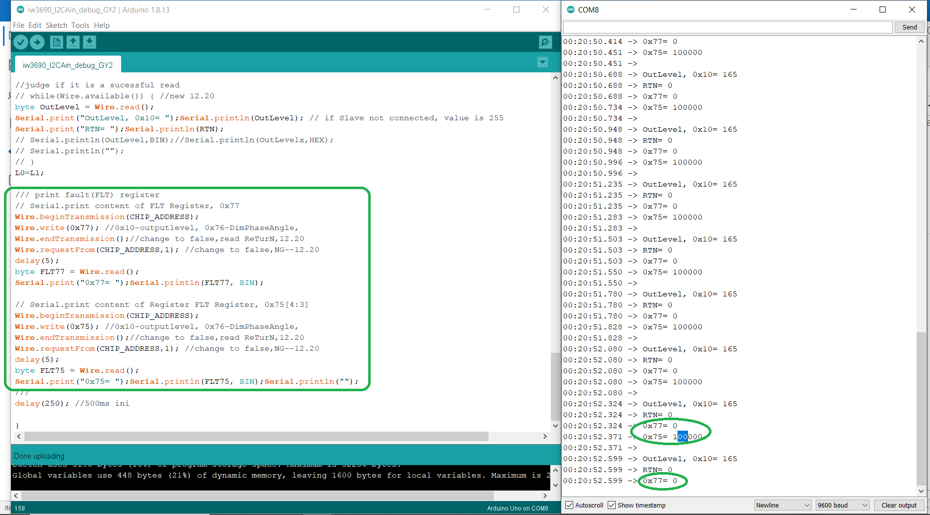
from iw3690 datasheet, I can't find temperature sensor related register, so I added code reading the fault of iw3690(0x77, 0x75[4:3]), from result it can be seen both fault register are OK, meaning no fault happens before the sketch stopping running.
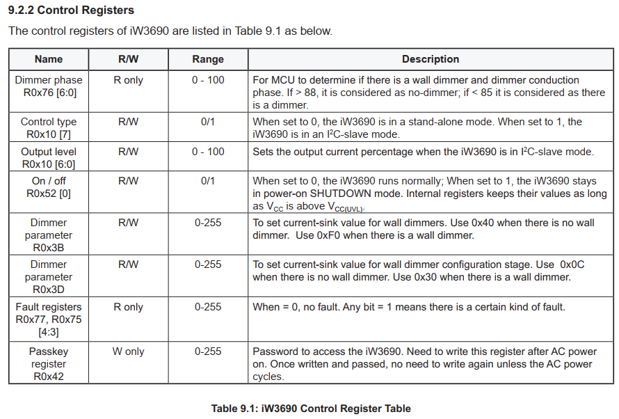
There is a temeperature sensor being used by the internal circuity; its value is not available to the user which I have seen later going throug the Register Set as given in the data sheets that you have mailed to me.
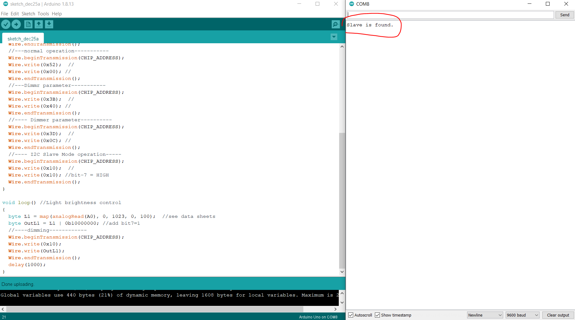
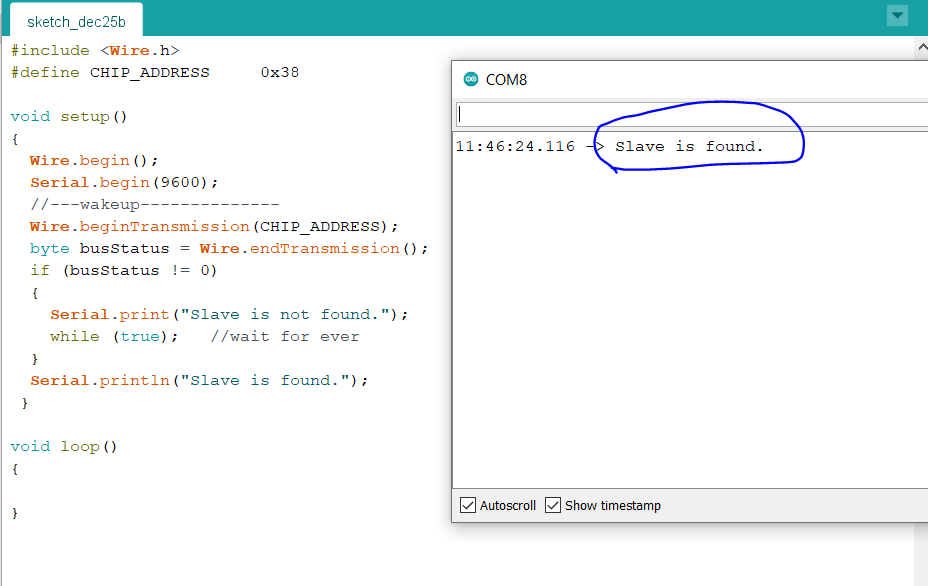
2. I have moderated your sketch of post #3 as follows, which you may upload in your UNO and then slowly turn the Potentiomter and see if the brighnress of the LED-array chnages. (What is the function of Passkey?) have you taken the phase-controlled AC output from the wall mounted Dimmer?
@GolamMostafa,
I have an idea to build a double dimmable type driver, phase cut dimming by triac+0-10V dimming via I2C, but the two kinds of dimming are not done at the same time.
for point 2, during I2C dimming situation, mains input is not phase-cut, so full mains is input.
I tried your sketch, result is "salve is not found". I guess the passkey may not be fully written.
when I add the other 2 data for passkey 0x42,
iw3690 can be found and sketch can run for a few minutes, after that it stops again, if I turn the variable resistor with screwdriver, LED light output doesn't change anymore.
I capture the logic from a module(Bluetooth) mounted on iw3690 demo, shows what is being done at start-up,
for passkey register, it is written 3 different data continuously.
I adde the code based on your previous sketch, it can run longer, from several minutes to ~15 minutes, but finally stops again. when code is running, I tuned the analog voltage and see the dimming is OK, the value of output level register proves the change of the LED brightness.
Have you wanted to mean that the writing of Passkey in a new/correct way has improved the performance of your system? If so, you can now tune your system going throuh the data sheets.
Do you have IW3690 chip (s) in your stock.
I am still not clear as to the role of Passkey, which has to be known through experiments as data sheets have not said much about it. In my country, the chip is not available to enable me to perform experiments.
Another phenomenon, it is same as before.
If 1s interval is set in the loop, code runs ~15min.
if interval is set to 0.33s, code runs ~3min, shorter than that of 1s interval then it stops.
I am wondering whether the sketch will be dead if UNO continuously sending data to slave Iw3690.
As I need to trace the Vanalog to adjust the LED current level in time w/o too much delay, the best interval is ~100ms for continuous update. To save the number of times of communication, that is why in my initial code, a judgement for Vanalog variation is added, if the Vanalog keeps same, i.e., Abs(ΔVanalog)<1,0x10 is not written again.
For iw3690, I will check if I can send you a demo board.