My intension is to play with stand-alone IW3690 which I am tryig to collect via Techshop Online Shopping.
iw3690 seems not widely been used by customers anymore, I am afraid you may not get it. More, iw3690 is a controller with protections, if the operational conditions are not met, it won't work. so let IC alone work is a bit difficult.
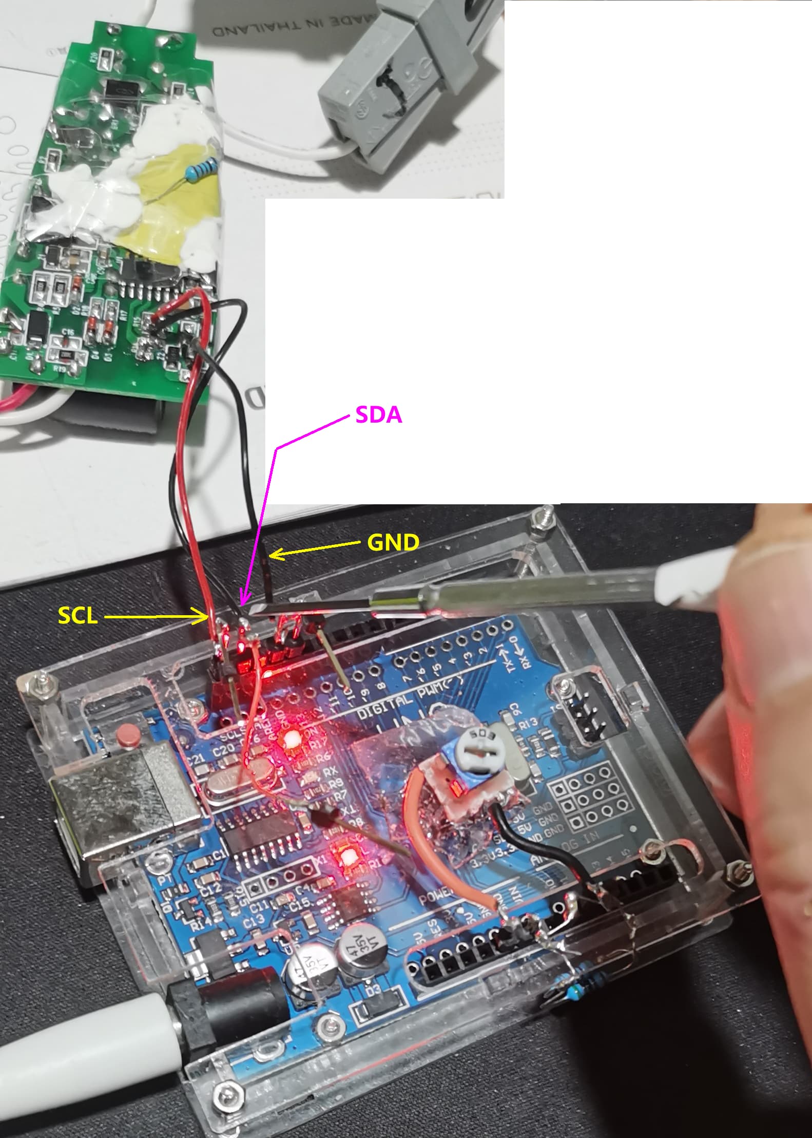
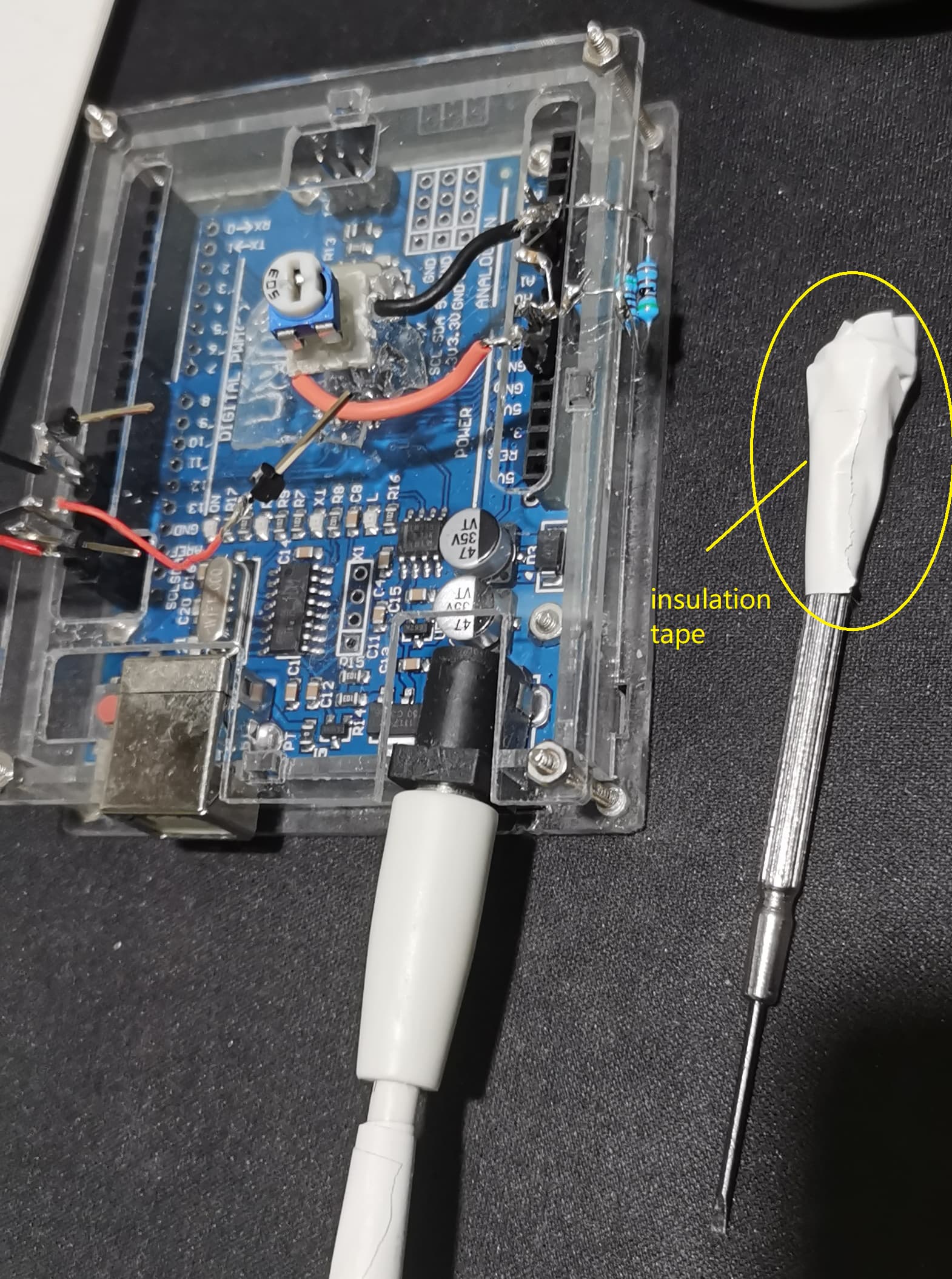
Just now I found an interesting thing. if the code stops running, I touch the SDA wire with the screw driver, the programing starts to work again, every time it is valid, but if screw driver touch SCL or GND, it is not valid. on the other end of the screwdriver, insulation tape is wrapped to protect from electric shocked. So I will try to insert an x0kOhm...x00 kOhm resistor between SDA and GND(or Earth? if Earth, higher resistance is needed) to see if it can help to solve the issue.
1 Like
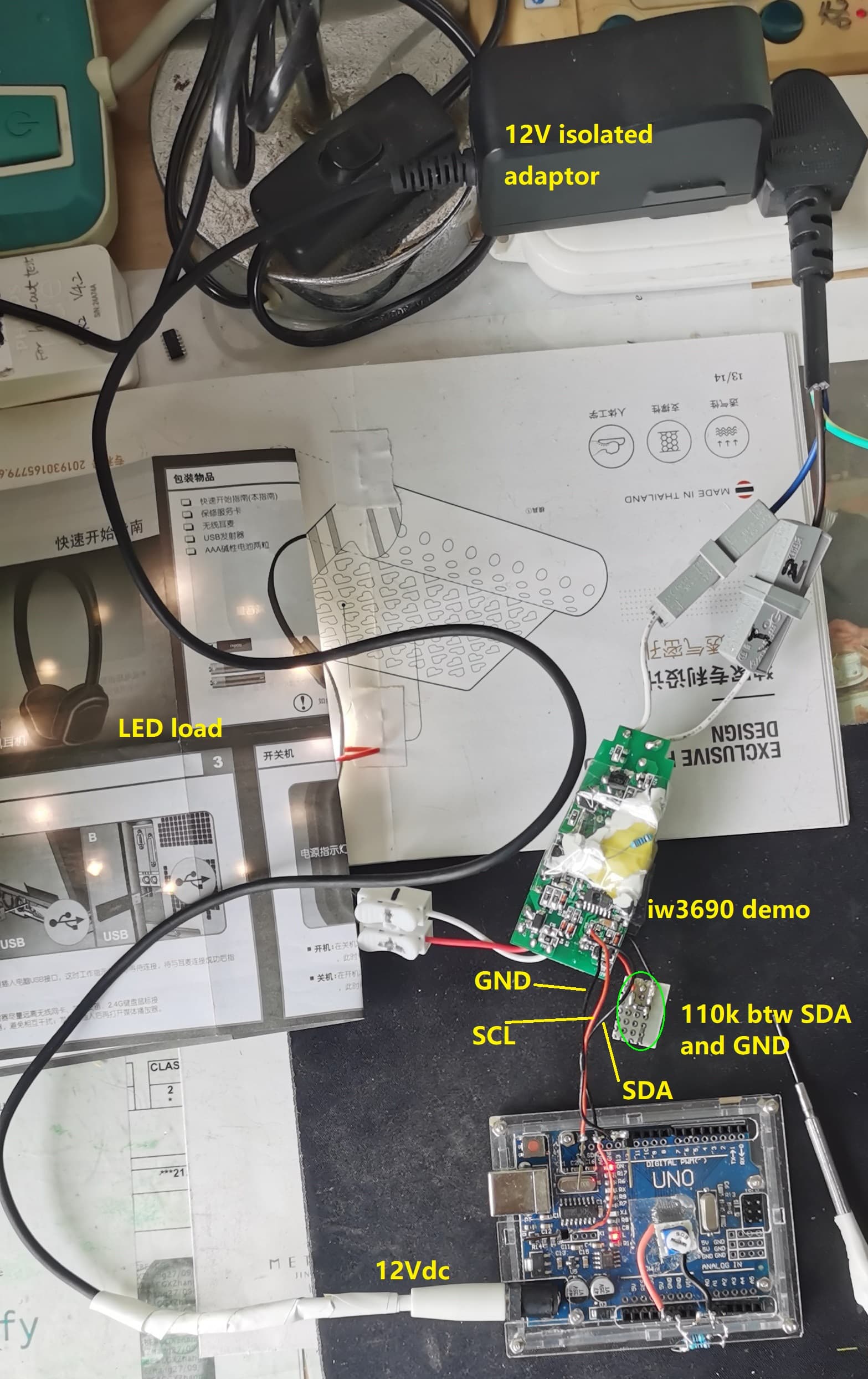
I added a 110kOhm btw. SDA and GND on iw3690 demo board, then I run the program again for twice, it continues working for 30min and 60min each without stopping. my setup is like below,
I also updated the latest code here, which is based on your proposal.
#include <Wire.h>
#define CHIP_ADDRESS     0x38
byte L0 = 0; //JZ added, 12.26

void setup()
{
  Wire.begin();
//  Wire.setClock(10000);//JZ added, 12.26: reduce Fclk, not valid
  Serial.begin(9600);

  delay(1200); //JZ added, 12.26:UNO output matches iw3690 timing

  //---wakeup--------------
  Wire.beginTransmission(CHIP_ADDRESS);
  byte busStatus = Wire.endTransmission();
  if (busStatus != 0)
  {
    Serial.print("Slave is not found.");
    while (true);   //wait for ever
  }
  Serial.println("Slave is found.");

  //----Passkey---------------------
  Wire.beginTransmission(CHIP_ADDRESS);
  Wire.write(0x42);
  Wire.write(0xA7);
  Wire.write(0x65);
  Wire.write(0x3F);
  Wire.endTransmission();

  Wire.beginTransmission(CHIP_ADDRESS);
Wire.write(0x42);  //0x42
Wire.write(0x65); //
Wire.endTransmission();
delay(2);
Wire.beginTransmission(CHIP_ADDRESS);
Wire.write(0x42);  //0x42
Wire.write(0x3F); //
Wire.endTransmission();
delay(2);

  //---normal operation-----------
  Wire.beginTransmission(CHIP_ADDRESS);
  Wire.write(0x52);  //
  Wire.write(0x00); //
  Wire.endTransmission();
  //---Dimmr parameter-----------
  Wire.beginTransmission(CHIP_ADDRESS);
  Wire.write(0x3B);  //
  Wire.write(0x40); //
  Wire.endTransmission();
  //---- Dimmer parameter----------
  Wire.beginTransmission(CHIP_ADDRESS);
  Wire.write(0x3D);  //
  Wire.write(0x0C); //
  Wire.endTransmission();
  //---- I2C Slave Mode operation-----
  Wire.beginTransmission(CHIP_ADDRESS);
  Wire.write(0x10);  //
  Wire.write(0x10); //bit-7 = HIGH
  Wire.endTransmission();
}

void loop() //Light brightness control
{

  byte L1 = map(analogRead(A0), 0, 1023, 0, 100);  //see data sheets
  byte OutL1 = L1 | 0b10000000; //add bit7=1
  //----dimming------------
  if(abs(L1-L0)>=1) //JZ added, 12.26:if No new dim input, no communication
  {
  Wire.beginTransmission(CHIP_ADDRESS);
  Wire.write(0x10);
  Wire.write(OutL1);
  Wire.endTransmission();
  Serial.println(OutL1,BIN);
  }
  delay(150);
  L0 = L1; //JZ added, 12.26: for comparison of dimming input
}
This topic was automatically closed 180 days after the last reply. New replies are no longer allowed.