The pin function of Arduino uno A4 and A5 works well as analog input but not working as I2c lines, the program has no errors and i have already used the i2c lines of the board and took the readings.
Before this problem if a connection is wrong with the INA209 the serial monitor shows the value 32.675 after correcting the connection the correct voltage and current comes up,,, But now the serial monitor is blank for I2C devices... I think the I2C pin of the controller is problem(but i am not conform)...
If u people have come across this please help me..
#include <Wire.h>              //I2C library
#include <INA209.h>            //INA209 library

INA209 ina209a(0x40);

const byte OUTPUT_PIN = 3;  // Timer 2 "B" output: OC2B

const byte n = 24;


void setup() {


  Serial.begin(9600);        // setup serial
  Wire.begin();              // join i2c bus
  pinMode(7,OUTPUT);
  pinMode(8,OUTPUT);

  // ------------- General Configuration ---------
  /* Configuration Register 00h (Read/Write)
   Default settings -> writeCfgReg(14751)
   Bus Voltage Range = 32V
   PGA (Shunt Voltage Only) = +/- 320mV
   BADC Bus ADC Resolution/Averaging = 12bit
   SADC Shunt ADC Resolution/Averaging = 12bit
   Operating Mode = Shunt and Bus, Continuos
   */
  ina209a.writeCfgReg(14751); // Default settings no averaging
  // ina209a.writeCfgReg(15839); // 8 averaging samples bus and shunt
  //ina209a.writeCfgReg(16247);       // 64 averaging samples bus and shunt

  // -------------- Calibration ------------------
  /* Calibration Register 16h (Read/Write)
   This register sets the current that corresponds to a full-scale drop across the shunt.
   Full-scale range and the LSB of the current and power measurement depend on the value entered in this register.
   See the Programming the INA209 Power Measurement Engine section of INA209 datasheet.
   In this example:
   Vbus_max = 32V
   Vshunt_max = 0,32V
   Rshunt = 0,05 Ohm
   ->  Max Expected Current = +/- 6A
   Current LSB = 200uA
   Calibration Reg = 4096
   Power LSB = 4mW
   Max Power = 204,8W
   */
  ina209a.writeCal(4096);

  // ---------- WARNING WATCHDOG REGISTERS -------
  /* These registers set warning limits that trigger flags in the Status Register
   and activate the Warning pin.
   */
  ina209a.writeShuntVolPwrn(30000);        // set Shunt Voltage Positive Warning limit to 30000 (= 300mV)
  ina209a.writeShuntVolNwrn(-500);         // set Shunt Voltage Negative Warning limit to -500 (= -5mV)
  ina209a.writePowerWrn(10000);            // set Power Warning limit
  ina209a.writeBusOVwrn(52000);            // set Bus Over-Voltage Warning limit, if you want a limit of 26V you have to set 26000*2 = 52000
  ina209a.writeBusUVwrn(10000);            // set Bus Under-Voltage Warning limit, if you want a limit of 5V you have to set 5000*2 = 10000

    // ---------- OVER-LIMIT/CRITICAL WATCHDOG REGISTERS ----------------
  /* These registers set the over-limit and critical DAC limits that trigger flags to be set in the Status Register
   and activate the Overlimit pin or the Critical pin.
   */
  ina209a.writePowerOL(12000);             // set Power Over-Limit
  ina209a.writeBusOVOL(60000);             // set Bus Over-Voltage Over-Limit, if you want a limit of 30V you have to set 30000*2 = 60000 (see the datasheet for other functions)
  ina209a.writeBusUVOL(6000);              // set Bus Under-Voltage Over-Limit, if you want a limit of 3V you have to set 3000*2 = 6000
  ina209a.writeCrShuntPV(51200);           // set Critical DAC+ Register (Critical Shunt Positive Voltage). No sign bit (sets a positive limit only). At full-scale range = 255mV; LSB = 1mV; 8-bit.
  // if you want a limit of +200mV you have to set 200*256 = 51200;
  // this register control GPIO PIN, see the datasheet.
  ina209a.writeCrShuntNV(51200);           // set Critical DAC– Register (Critical Shunt Negative Voltage). No sign bit (sets negative limit only). At full-scale range = –255mV; LSB = 1mV; 8-bit.
  // if you want a limit of -200mV you have to set 200*256 = 51200;
  // this register control DAC Comparator output filter, see the datasheet.

  pinMode (OUTPUT_PIN, OUTPUT);

   TCCR2A = _BV (WGM20) | _BV (WGM21) | _BV (COM2B1); // fast PWM, clear OC2A on compare
  TCCR2B = _BV (WGM22) | _BV (CS20) | _BV (CS21);
//  TCCR2B = _BV (WGM22) | _BV (CS21);
  OCR2A =  n;

OCR2B =15 ;
}


void loop()
{

     Serial.println("input");
    Serial.println(msg2dot3(ina209a.busVol()));   // show Voltage measured
    Serial.println(msg2dot3(current_mA(200)));   // show Current measured
    Serial.println (msg3dot3(power_mW(4)));        // show Power measured


  }


int current_mA (int current_LSB) {          // set Current in mA, current_mA = ina209a.current() * current_LSB (uA) / 1000
  int y = 10000 / current_LSB;
  int x = ina209a.current() / y;
  return x;
}

long power_mW (int power_LSB) {              // set Power in mW, power_mW = ina209a.power() * power_LSB (mW)
  long x = ina209a.power() * power_LSB;
  return (x/10);
}

String msg2dot3 (int xvalue) {              // format integer to string 2.3 character
  String strvalue = 0;
  if (xvalue >= 0){
    strvalue = String (xvalue);
    switch (strvalue.length())
    {
    case 1:
      strvalue = String (" .00" + strvalue.substring(0));
      break;
    case 2:
      strvalue = String (" .0" + strvalue.substring(0));
      break;
    case 3:
      strvalue = String (" ." + strvalue.substring(0));
      break;
    case 4:
      strvalue = String (" " + strvalue.substring(0,1) + "." + strvalue.substring(1));
      break;
    case 5:
      strvalue = String (strvalue.substring(0,2) + "." + strvalue.substring(2));
      break;
    default:
      strvalue = String ("error");
    }
  }
  else {
    strvalue = String (abs(xvalue));
    switch (strvalue.length())
    {
    case 1:
      strvalue = String (" -.00" + strvalue.substring(0));
      break;
    case 2:
      strvalue = String (" -.0" + strvalue.substring(0));
      break;
    case 3:
      strvalue = String (" -." + strvalue.substring(0));
      break;
    case 4:
      strvalue = String ("-" + strvalue.substring(0,1) + "." + strvalue.substring(1));
      break;
    case 5:
      strvalue = String (strvalue.substring(0,2) + "." + strvalue.substring(2) + "-");
      break;
    default:
      strvalue = String ("error");
    }
  }
  return strvalue;
}

String msg3dot3 (long pvalue) {              // format long integer to string 3.3 character
  String strvalue = 0;
  strvalue = String (pvalue);
  switch (strvalue.length())
  {
  case 1:
    strvalue = String (" .00" + strvalue.substring(0));
    break;
  case 2:
    strvalue = String (" .0" + strvalue.substring(0));
    break;
  case 3:
    strvalue = String (" ." + strvalue.substring(0));
    break;
  case 4:
    strvalue = String (" " + strvalue.substring(0,1) + "." + strvalue.substring(1));
    break;
  case 5:
    strvalue = String (" " +strvalue.substring(0,2) + "." + strvalue.substring(2));
    break;
  case 6:
    strvalue = String (" " +strvalue.substring(0,3) + "." + strvalue.substring(3));
    break;
  default:
    strvalue = String ("error");
  }
  return strvalue;
}
that is only one device so i have not connected any pull up resistors
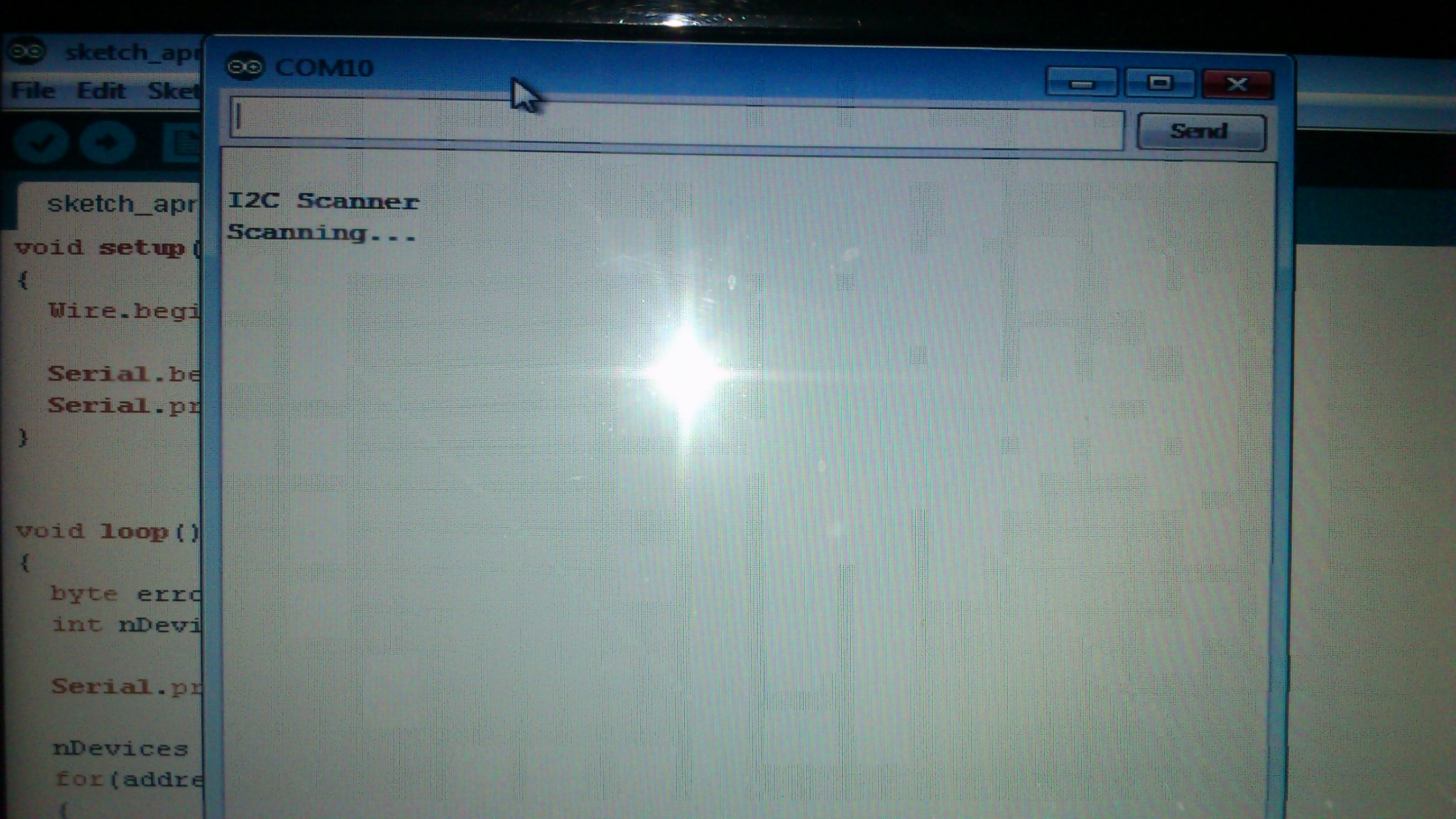
i Changed the address to 1001000 for the tmp ic ,, and i also tried the I2C scanner . i have uploded the pics.... the serial monitor prints the first two lines...
remember :
in the requestFrom(address, count) description :
address: 8 bit integer, or an int value (ints are 16 bits long by default). This is the address of an I2C slave that the ATmega will communicate with. It is cast to an 8-bit unsigned integer. If given an integer (16 bit) value, the number will have its most significant 8 bits truncated. The address is then shifted left one bit, so only the least significant 7 bits are used. If you do have an address with 8 bits, you must shift your address to the right (drop the lowest bit) in order to use it with the Arduino.