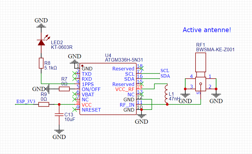
Hi, I have designed a custom board that integrates the ATGM336H-5N31 GNSS module.
I am trying to talk to the chip with I2C, but my microcontroller can't find the chip (it can find my I2C accelerometer). I was wondering if someone maybe has some experience with the I2C on this chip, because I only see everyone talking to it with UART. Or if someone maybe knows something I can try.
If someone can help me with this, that would be great!
Some remarks:
The LED I tied to the 1pps pin is blinking (the GPS & module work).
The main microcontroller is an ESP32 S3
The reason that I thought it had I2C was because it has SCL and SDA pins, but I can't find any info on this in the datasheet.
I have tied the "ON/OFF" pin to ground because I think the chip is active low, but the datasheet was (I think) translated from Chinese, so I don't know if this is actually correct. (I also tried to connect it to 3V3, but that didn't change anything, I think)
What is out there is that this module can do UART/I2C/SPI. However no mention about I2C address! Uart will definitely work, but if you wanna try I2C anyway, take a look at this:
I have not specified a speed in wire.h, do you think this matters for discovery of devices? If so, I will try with 5k pull-ups. (I can only check this in a few days probably though).
And do you think that the connection to ground from the ON/OFF pin is correct? Or do you think it has to be tied to 3v3?
I have tied the ON/OFF line to GND and 3v3, while holding 2 10k resistors against the existing 10k resistors (making them 5k), but unfortunately nothing changed...
It did still find my IMU though, so I did not break anything in the process
Shooting in a random direction in the woods rarely hit any prey, and that's what you're dealing with here. Since you haven't establish if the device really is on, how about hooking it up over serial instead and see if you get anything there.