Hello,
So I have quite a question. I am building a modular macropad with an Arduino nano ESP32. The idea is that there are different modules that can move. For the Arduino to know when which button is pressed, or which potentiometer is turned, I use different PCB's each with an ATMega328P-PU.
On the module with the Arduino is also a display, this, and the ATMega's, communicate with I²C. The problem is that they just don't want to work together. In the code is a custom library, I will add it here, but it doens't do anything major to this problem.
code for the arduino:
/*
*
*/
#include <BleCombo.h> //library to establish BLE HID connection
#include <time.h> //include time library
#include <WiFi.h> //include wifi library
#include <Adafruit_GFX.h> //library to print and draw on the OLED-display
#include <Adafruit_SSD1306.h> //library to establish connection with the OLED-display
#include <Wire.h> //library to establish I²C connection
#include <GIP.h>
#define SCREEN_WIDTH 128 //OLED display width, in pixels
#define SCREEN_HEIGHT 32 //OLED display height, in pixels
#define OLED_RESET -1 //variable to connect the screen with reset (needs to be -1 to share reset)
#define SCREEN_ADDRESS 0x3C //adress of the OLED-display
#define battery_port A0 //port to read the battery level
#define switch_chip 1
#define slide_chip 2
#define rotation_chip 3
#define joystick_chip 4
#define string_length 7
const char* ssid = "Stemnet"; //define the wifi adress
const char* password = ""; //define the wifi password
long timezone = 0; //set the timezone
byte daysavetime = 1; //set the day
struct tm tmstruct; //make a time structure
Adafruit_SSD1306 display(SCREEN_WIDTH, SCREEN_HEIGHT, &Wire, OLED_RESET); //start communication with the OLED-display
mechanical_switch switch00(10);
mechanical_switch switch01(11);
mechanical_switch switch02(12);
mechanical_switch switch03(13);
mechanical_switch switch10(14);
mechanical_switch switch11(15);
mechanical_switch switch12(16);
mechanical_switch switch13(17);
mechanical_switch switch20(18);
mechanical_switch switch21(19);
mechanical_switch switch22(20);
mechanical_switch switch23(21);
mechanical_switch switch30(22);
mechanical_switch switch31(23);
mechanical_switch switch32(24);
mechanical_switch switch33(25);
bool wifi_connected = false; //this boolean will be set true when the arduino is connected to the wifi
char cursor_place = 0; //variable to store the position of the OLED cursor
char battery_level = 100; //variable to store the previous send battery level
char real_battery = 100; //variable to check the battery level with the send level
char I2C_count = 0; //variable that adds up with each incomming byte
char I2C_check = 0;
char I2C_chip_adress = 0;
char I2C_interface_adress = 0;
char last_read = 0;
void setup() {
Keyboard.begin(); //make a Keyboard object
Mouse.begin(); //make a Mouse object
display.begin();
Wire.begin();
switch00.begin(0x80, 0x82, 0x81, 0x41);
switch01.begin(0x80, 0x82, 0x81, 0x42);
switch02.begin(0x80, 0x82, 0x81, 0x43);
switch03.begin(0x80, 0x82, 0x81, 0x44);
switch10.begin(0x80, 0x82, 0x81, 0x45);
switch11.begin(0x80, 0x82, 0x81, 0x46);
switch12.begin(0x80, 0x82, 0x81, 0x47);
switch13.begin(0x80, 0x82, 0x81, 0x48);
switch20.begin(0x80, 0x82, 0x81, 0x49);
switch21.begin(0x80, 0x82, 0x81, 0x50);
switch22.begin(0x80, 0x82, 0x81, 0x51);
switch23.begin(0x80, 0x82, 0x81, 0x52);
switch30.begin(0x80, 0x82, 0x81, 0x53);
switch31.begin(0x80, 0x82, 0x81, 0x54);
switch32.begin(0x80, 0x82, 0x81, 0x55);
switch33.begin(0x80, 0x82, 0x81, 0x56);
pinMode(battery_level, INPUT); //make the battery level port input
pinMode(7, INPUT);
if(!display.begin(SSD1306_SWITCHCAPVCC, SCREEN_ADDRESS)){ //if the internal OLED display voltage isn't 3.3V, don't stop the loop protect the OLED display
Serial.println("ERROR: 1D1"); //print the error on the serial monitor
for(;;); //go in an infinite loop
}
display.setTextSize(1); //set the standard text size to 1
display.setTextColor(WHITE); //set the standard text color to white
display.clearDisplay(); //clear the display
display.setTextSize(2); //set the text size to 2
display.setCursor(2, 2); //set the cursor on the display to pixel 2, 2
display.print("START-UP"); //print text
display.display(); //display text
delay(750); //wait 1.5 seconds
display.clearDisplay(); //clear the display
display.setTextSize(1); //set the text size to 1
display.setCursor(2, 2); //set the cursor on the display to pixel 2, 2
display.print("connect to:"); //print text
display.setCursor(2, 15); //set the cursor on the display to pixel 50, 2
display.print(ssid); //print the name of the wifi network
display.display(); //display the text
delay(500); //delay 0.5 seconds
WiFi.begin(ssid, password); //start to connect to the wifi network
display.setCursor(2, 30); //set the cursor on the display to pixel 2, 10
while(WiFi.status() != WL_CONNECTED && cursor_place < 52 ){ //while the arduino isn't connected to the wifi network the cursor_place makes sure it doesn't take too long
display.setCursor(cursor_place, 25); //set the cursor on the display to pixel 2, 20
display.print("."); //print text
display.display(); //display the text
cursor_place = cursor_place + 5; //change the cursor by 5 pixels
delay(500); //delay 0.5 seconds
}
if(cursor_place >= 52){ //if it took too long to connect to the wifi
display_error("1W1"); //display the error message
wifi_connected = false; //make sure that the wifi_connected variable is set false
}
else{
wifi_connected = true; //make the variable that indicates if the arduino is connected with wifi true
}
if(wifi_connected){ //if the WiFi is connected
display.clearDisplay(); //clear the display
display.setTextSize(2); //set the text size to 2
display.setCursor(2, 2); //set the cursor on the display to pixel 2, 2
display.print("CONNECTED"); //print text
display.display(); //display text
delay(750); //wait 1.5 seconds
display.clearDisplay(); //clear the display
display.setTextSize(1); //set the text size to 1
display.setCursor(2, 2); //set the cursor on the display to pixel 2, 2
display.print("IP-adress:"); //print text
display.setCursor(2, 15); //set the cursor on the display to pixel 50, 2
display.print(WiFi.localIP()); //print the name of the wifi network
display.display(); //display the text
delay(1500); //delay 1.5 seconds
display.clearDisplay(); //clear the display
display.setTextSize(1); //set the text size to 1
display.setCursor(2, 2); //set the cursor on the display to pixel 2, 2
display.print("CONTACT TIME SERVER"); //print text
display.display(); //display text
delay(750); //wait 1.5 seconds
configTime(3600*timezone, //configure the timezone
daysavetime*3600, //configure the daytime
"time.nist.gov", //configure the time
"0.pool.ntp.org", //configure the time
"1.pool.ntp.org"); //configure the time
delay(200); //delay 200 milliseconds
char buffer[30]; //create a string to store the date and time in
getLocalTime(&tmstruct, 5000); //get the time
sprintf(buffer,"%d-%02d-%02d, %02d:%02d:%02d", //store the time in the variable with the right index
(tmstruct.tm_year)+1900, //store the year
( tmstruct.tm_mon)+1, //store the month
tmstruct.tm_mday, //store the day
tmstruct.tm_hour , //store the hour
tmstruct.tm_min, //store the minute
tmstruct.tm_sec); //store the second
display.clearDisplay(); //clear the display
display.setTextSize(1); //set the text size to 1
display.setCursor(2, 2); //set the cursor on the display to pixel 2, 2
display.print("LOCAL TIME:"); //print text
display.setCursor(2, 15); //set the cursor on the display to pixel 50, 2
display.print(String(buffer)); //print the name of the wifi network
display.display(); //display the text
delay(1500); //delay 1.5 seconds
}
display.clearDisplay(); //clear the display
display.setTextSize(2); //set the text size to 2
display.setCursor(2, 1); //set the cursor on the display to pixel 2, 1
display.print("START-UP"); //print text
display.setCursor(2, 18); //set the cursor on the display to pixel 2, 18
display.print("COMPLETE"); //print text
display.display(); //display text
delay(1500); //wait 1.5 seconds
display.clearDisplay(); //clear the display
display.display(); //display the empty screen
}
void loop() {
if(WiFi.status() == WL_CONNECTED){
wifi_connected == true;
}
else{
wifi_connected == false;
}
if(Keyboard.isConnected()) { //if the arduino is connected with BLE
real_battery = map(analogRead(battery_port), 0, 1023, 0, 100); //store the battery level in percentage
if(real_battery != battery_level){ //if the last sent is not the real battery level
Keyboard.setBatteryLevel(real_battery); //set the battery level to the correct level
battery_level = real_battery; //make the variable the right percentage
}
Wire.requestFrom(1, 6);
I2C_interface_adress = last_read * 10;
last_read = Wire.read();
I2C_interface_adress = I2C_interface_adress + last_read;
if(switch00.get_adress() == I2C_interface_adress){
switch00.pressed();
}
else if(switch01.get_adress() == I2C_interface_adress){
switch01.pressed();
}
else if(switch02.get_adress() == I2C_interface_adress){
switch02.pressed();
}
else if(switch03.get_adress() == I2C_interface_adress){
switch03.pressed();
}
else if(switch10.get_adress() == I2C_interface_adress){
switch10.pressed();
}
else if(switch11.get_adress() == I2C_interface_adress){
switch11.pressed();
}
else if(switch12.get_adress() == I2C_interface_adress){
switch12.pressed();
}
else if(switch13.get_adress() == I2C_interface_adress){
switch13.pressed();
}
else if(switch20.get_adress() == I2C_interface_adress){
switch20.pressed();
}
else if(switch21.get_adress() == I2C_interface_adress){
switch21.pressed();
}
else if(switch22.get_adress() == I2C_interface_adress){
switch22.pressed();
}
else if(switch23.get_adress() == I2C_interface_adress){
switch23.pressed();
}
else if(switch30.get_adress() == I2C_interface_adress){
switch30.pressed();
}
else if(switch31.get_adress() == I2C_interface_adress){
switch31.pressed();
}
else if(switch32.get_adress() == I2C_interface_adress){
switch32.pressed();
}
else if(switch33.get_adress() == I2C_interface_adress){
switch33.pressed();
}
if(wifi_connected){ //if the arduino is connected to a wifi network
display_time(); //go to the display_time void0x3C
}
}
delay(10);
}
void display_error(String error_message){ //void to display error messages
display.clearDisplay(); //clear the display
display.setTextSize(4); //set the text size to 2
display.setCursor(2, 2); //set the cursor on the display to pixel 2, 2
display.print(error_message); //print the error message
display.display(); //display the error message
delay(5000); //delay 5 seconds
display.clearDisplay(); //clear the display
display.display(); //display the clear display
}
void display_time(){ //void to display the time
char buffer[30]; //create a string to store the date and time in
getLocalTime(&tmstruct, 5000); //get the time
sprintf(buffer,"%02d:%02d:%02d", //store the time in the variable with the right index
tmstruct.tm_hour , //store the hour
tmstruct.tm_min, //store the minute
tmstruct.tm_sec); //store the second
display.clearDisplay(); //clear the display
display.setTextSize(2); //set the text size to 2
display.setCursor(2, 2); //set the cursor on the display to pixel 2, 2
display.print(String(buffer)); //print the time
getLocalTime(&tmstruct, 5000); //get the time
sprintf(buffer,"%d/%02d/%02d", //store the time in the variable with the right index
tmstruct.tm_mday, //store the day
(tmstruct.tm_mon)+1, //store the month
(tmstruct.tm_year)+1900); //store the year
display.setTextSize(1); //set the text size to 1
display.setCursor(2, 25); //set the cursor on the display to pixel 2, 20
display.print(String(buffer)); //print the date
display.display(); //display the text
delay(10); //delay 10 milliseconds
}
the code for the ATmega:
#include <Wire.h>

#define chip_adress 1

char interface_adress = 0;
bool pressed = false;


void setup() {

  Wire.begin(1);                                              // join i2c bus with address #8
  Wire.onRequest(requestEvent);                               // register event

  pinMode(0, INPUT);
  pinMode(1, INPUT);
  pinMode(2, INPUT);
  pinMode(3, INPUT);
  pinMode(4, INPUT);
  pinMode(5, INPUT);
  pinMode(6, INPUT);
  pinMode(7, INPUT);
  pinMode(8, INPUT);
  pinMode(9, INPUT);
  pinMode(10, INPUT);
  pinMode(11, INPUT);
  pinMode(12, INPUT);
  pinMode(13, INPUT);
  pinMode(A0, INPUT);
  pinMode(A1, INPUT);

}

void loop() {

  delay(1);

}

void requestEvent(){

    for(char i = 0; i > 13; i++){

    if(digitalRead(i) == HIGH){

      pressed = true;
      interface_adress = (10 + i);

    }

    if(pressed == true){

      Wire.write(interface_adress);

    }
  }/*

  if(analogRead(A0) > 900){

    Wire.beginTransmission(8);
    Wire.write(9712497);
    Wire.endTransmission();

  }

  if(analogRead(A1) > 900){

    Wire.beginTransmission(8);
    Wire.write(9712597);
    Wire.endTransmission();

  }*/

}
and the library:
GIP.h
/*
 *  This library is used in an GIP, it is made for these requirements and will not be updated after completion.
*/


#ifndef GIP_h
#define GIP_h

#include "Arduino.h"

#endif

class mechanical_switch{

    public:

        mechanical_switch(char adress);
        void begin(char character1, char character2, char character3, char character4);
        void pressed();
        char get_adress();


    private:

        char _adress;
        char _character1;
        char _character2;
        char _character3;
        char _character4;

};


class potentio{

    public:

        potentio(char adress);
        void begin( char character1_more,
                    char character2_more,
                    char character3_more,
                    char character4_more,
                    char character1_less,
                    char character2_less,
                    char character3_less,
                    char character4_less);
        void changed(char value);
        char get_adress();

    private:

        char _adress;
        char _character1_more;
        char _character2_more;
        char _character3_more;
        char _character4_more;
        char _character1_less;
        char _character2_less;
        char _character3_less;
        char _character4_less;
        char _value;
        char _percent;
        char _previous;

};
GIP.cpp:
/*
 * it is important to add the library 'BLECombo' to the main file to ensure the working of the library.
*/

#include "Arduino.h"
#include "GIP.h"
#include <BleCombo.h>

mechanical_switch::mechanical_switch(char adress){

    _adress = adress;

}

void mechanical_switch::begin(char character1, char character2, char character3, char character4){

    _character1 = character1;
    _character2 = character2;
    _character3 = character3;
    _character4 = character4;

}

void mechanical_switch::pressed(){

        Keyboard.press(_character1);
        Keyboard.press(_character2);
        Keyboard.press(_character3);
        Keyboard.press(_character4);
        delay(25);
        Keyboard.releaseAll();

}

char mechanical_switch::get_adress(){

    return _adress;

}


potentio::potentio(char adress){

    _adress = adress;

}

void potentio::begin(char character1_more,
                     char character2_more,
                     char character3_more,
                     char character4_more,
                     char character1_less,
                     char character2_less,
                     char character3_less,
                     char character4_less){

    _character1_more = character1_more;
    _character2_more = character2_more;
    _character3_more = character3_more;
    _character4_more = character4_more;
    _character1_less = character1_less;
    _character2_less = character2_less;
    _character3_less = character3_less;
    _character4_less = character4_less;

}

void potentio::changed(char value){

    _value = value;
    _percent = map(_value, 0, 255, 0, 100);

    if(_percent < _previous){

        while(_percent != _previous){

            Keyboard.press(_character1_less);
            Keyboard.press(_character2_less);
            Keyboard.press(_character3_less);
            Keyboard.press(_character4_less);
            delay(25);
            Keyboard.releaseAll();

            _previous--;

        }
    }
    if(_percent > _previous){

        while(_percent != _previous){

            Keyboard.press(_character1_more);
            Keyboard.press(_character2_more);
            Keyboard.press(_character3_more);
            Keyboard.press(_character4_more);
            delay(25);
            Keyboard.releaseAll();

            _previous++;

        }
    }
}

char potentio::get_adress(){

    return _adress;

}
The problem is that if i press a button on the ATMega's port (to make it high), nothing happens. I have tried to visualize the I²C with an osciloscope, but that didn't work really. So I don't know if the ATMega is ever asked to send the results. The display works fine, but the ATMega doesn't. I have tried different things with various results, but this is the program where the most seems to work.
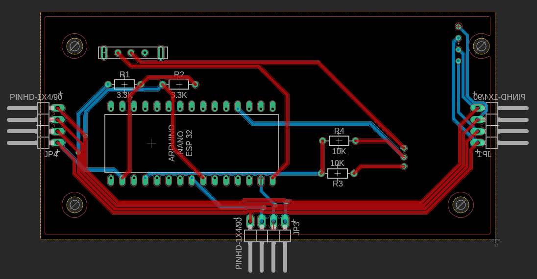
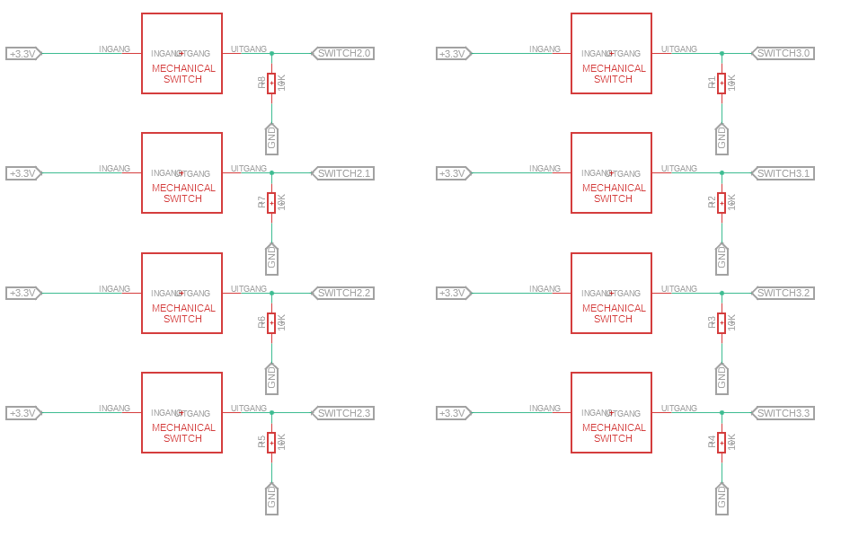
it is a simple circuit:

Is there anybody who knows why this doesn't work? If you have any questions, ask them please. I am doing this for a school project and I need to make some progress.
Thank you.
Siebe