All I get in Comms is a minus value showing which way the encoder has turned.... how do I code distance so it displays in millimetres please?
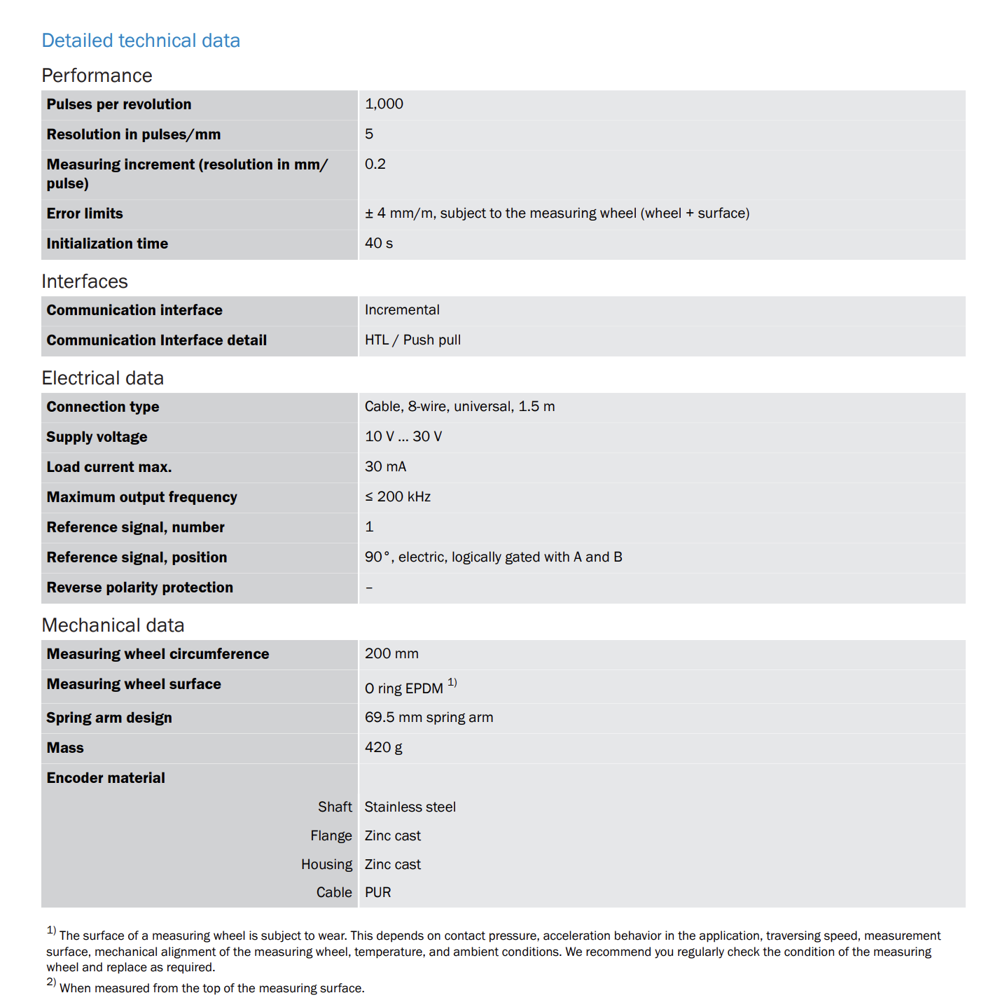
Please give a link to the encoder datasheet.
If you sum up the pluses and minuses into a count value, you then multiply that sum by a conversion factor of millimeters per count.
thanks for your feedback, this makes sense, I will try and give you feedback..... thank you very much
Post the code you have. Use Code Tags!
1 Like
It looks like you have the usual rotary encoder with A, B and Z signals. It's not clear how the positive and inverted signals have to be interpreted. An application note were helpful.
Did you try the Encoder library Basic example?
/* Encoder Library - Basic Example
 * http://www.pjrc.com/teensy/td_libs_Encoder.html
 *
 * This example code is in the public domain.
 */

#include <Encoder.h>

// Change these two numbers to the pins connected to your encoder.
//   Best Performance: both pins have interrupt capability
//   Good Performance: only the first pin has interrupt capability
//   Low Performance:  neither pin has interrupt capability
Encoder myEnc(5, 6);
//   avoid using pins with LEDs attached

void setup() {
  Serial.begin(9600);
  Serial.println("Basic Encoder Test:");
}

long oldPosition  = -999;

void loop() {
  long newPosition = myEnc.read();
  if (newPosition != oldPosition) {
    oldPosition = newPosition;
    Serial.println(newPosition);
  }
}
Your data sheet indicates that this encoder provides a voltage signal output (HTL/PushPull) equal to the 10-30V supply voltage.
These levels are too high for direct connection to the Arduino and can damage it.
Can you please provide information about how you have the encoder powered, and how it is connected to the Arduino.
1 Like
Good catch:
Incremental Encoder Signals: HTL (Push-Pull) or TTL (RS422) recommends using a diode to turn an HTL signal into an open collector compatible signal.
The conversion factor would depend on the pulses per mm (5pulse/mm per the datasheet) and the counts per pulse you get from the encoder, which, with the encoder library, depends on how many interrupt pins you are using for connecting the A & B signals. If you use no interrupts, the conversion factor would be 1/5mm/count, with one interrupt: 1/10mm/count, and with two interrupts: 1/20mm/count.
I have the encoder powered via a bench power supply, Im using 12 volts connected to the red wire with blue connected to ground. The 2 inputs White and purple are connected to the Arduino.
thanks for your feedback, I will try this sketch as soon as Im back at my station
Essentially what im trying to achieve.... Im trying to create a dosing system i.e. every metre send a HIGH signal to my dosing gun. Assuming I can read the encoder Im going to use push buttons to select whether its every one metre, two metres etc..... after that I would like to expand the project and look at controlling the dosing system using a touch screen.....
However ![]() I have a lot to learn and a long way to go yet....
I have a lot to learn and a long way to go yet....
I think this wiring has put 12v to the inputs of the Arduino and you may have damaged them.
I'm not a hardware guy, but I think you want to use a high speed photo diode like the 6n137 between the outputs of the encoder and the inputs of the Arduino.
You may get better hardware advice from some of the other posters.
You can put a small signal diode, cathode toward the encoder signal, anode end to the pin to bock the 12V encoder signal from feeding into the pin. Then a pullup or INPUT_PULLUP on the pin should hold the pin high unless the encoder LOW signal pulls it LOW.
Do you know of a logic family that supports input voltages in the range of the sensor power requirements?
The signals may be open collector, current loop or differential, independent from the supply voltage. It's not hard to measure the logic levels on the signal pins, with or without pullup resistors.
Thanks for this advice, Serial Comms is actually giving me an incremental value as I turn the encoder. Though I have noticed, depending on the speed of the encoder, the value range changes per 1 rotation.... ie if I spin it slowly for one rotation I may have a range of 90, If I spin it quickly 1 rotation will give me a value in the 100s.
Ive found changing the Baud rate gives me more sensitive values.
I just need to know how to reset the count at a value I define.... If/Else maybe?

using Interrupt Pins make these values so sensitive, I've found its more settled using nether
Ths could be some kind of bounce. If the internals of that encoder are mechanical, you might have some contact bounce giving spurious signals. Or maybe it is a "floating input" issue. How do you have the 12V totem-pole signal wired up to your arduino? With a blocking diode to protect it? If so are you using an external or internal pullup (e.g. pinMode(pin,INPUT_PULLUP)) to put a definite logic level on the pin?
Using a modern baud rate like Serial.begin(115200); would help the printing not interfere with other opertations.
If you are not using interrupts and are using a slow baud, you'll miss transitions and lose accuracy.
The Encoder Library, for Measuring Quadarature Encoded Position or Rotation Signals doc suggests:
myEnc.write(newPosition);
Set the accumulated position to a new number.
sorry, just read this. I have 12V coming from my Bench Power Supply to the Encoder.... from the Encoder I have 2 resistors Ive soldered together.... 1 x 4.7 kOhms and 1 x 6.8kOhms in a bread board with my inputs going from the breadboard to my Mega 2560. Ive measured the voltage coming through to the Dev board and it seems to idle from 4.8V to about 5.3V..... would this fluctuation be whats causing inconsistancies? Or is the resistor setup the wrong way to reduce the voltage?
I only started learning a couple of months ago and Im on a big learning curve....![]()
Is the MOFSET way a better way?