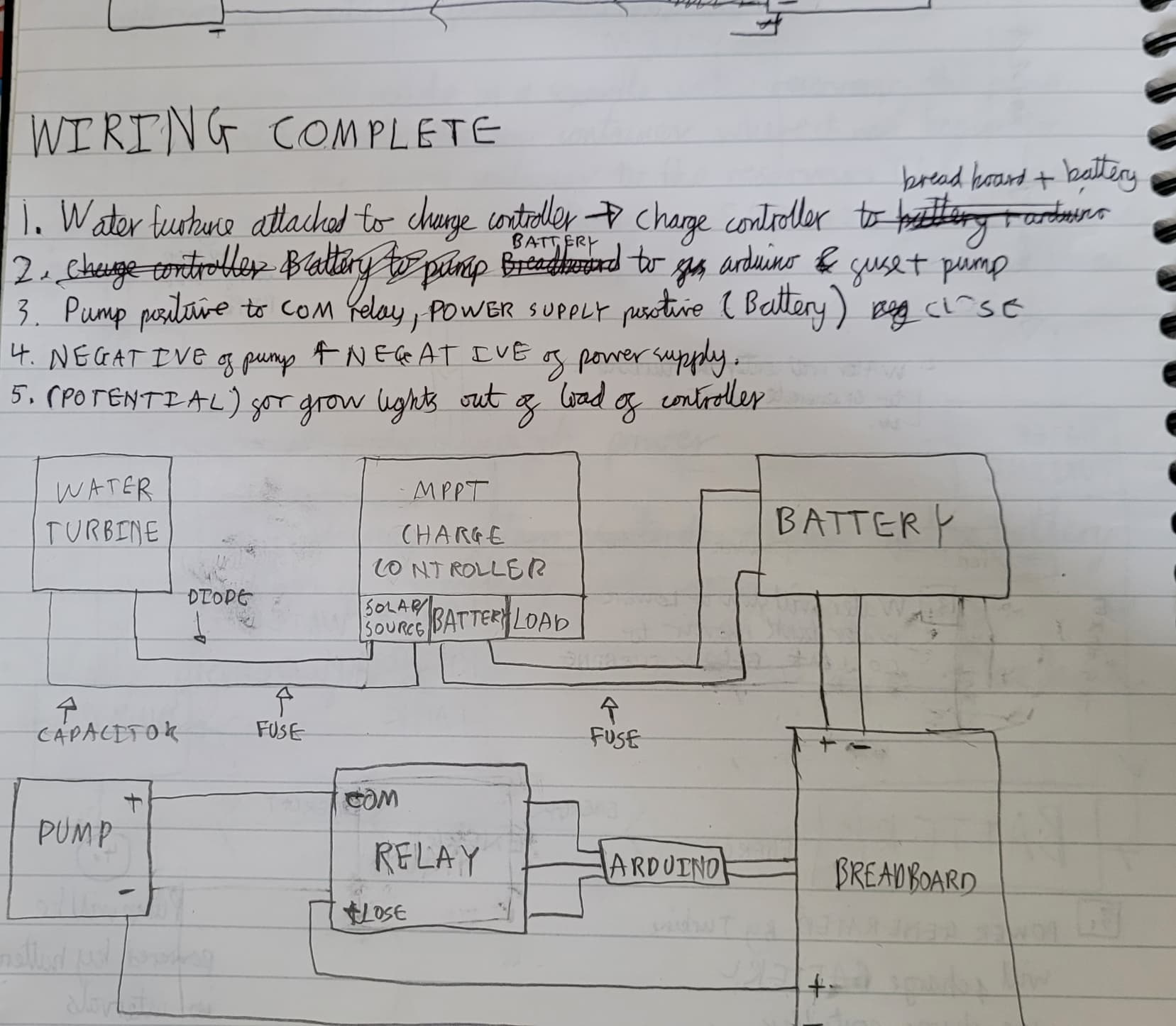
Will this wiring work?
I wanted to charge the battery while also being used in intervals.
That is correct. Every MPPT-based Solar, Hydro, or Wind system looks like this, except that most will have an Inverter where the breadboard is to provide AC.
The only thing I would change is to replace the breadboard with more robust connectors. I used Marine Bus Bars.
I just noticed you appear to be powering the relay coil from the Arduino. That is not a good idea, power the coil from the battery so only one digital control wire and Ground between Arduino and Relay coil.
I am sorry but I don't really know how to do that, I drew it like this for my own personal understanding
are u able to do a basic sketch to show what you mean?
Is there any precaution I have to take or a certain way I have t wire it to use the battery while it is charging or is diagram ok?
how would I wire the battery to the breadboard/ connector if both terminals are connected to the mppt controller
I will put together a sketch when I have a free moment, but any solar power resource should be helpful.
The simple answer is NO bec ause the MPPT takes care of that. The more acedemic long winded explanation is of course.
Not sure what you mean.
The simple answer is the MPPT is charging the battery. At the same time the Battery is providing power to the Pump (conditionally) you could also use that battery to provide the relay coil power or use the pins as you have.
I will change my mind and agree with your choice of a 5VDC relay like this one.
https://amz.cx/3VO8
NOTE this is Canadian listing, change link to your country.
Here is my poor drawing. I think it is the same as yours, except get rid of the breadboard. If this is going to be outside of conditioned space, use Marine Grade Bus Bars, breakers, disconnects and use double-walled heat shrink with maximum overlap on all connections. They contain glue as they must be air-tight to stop corrosion. Also, any bolts or other connectors should be coated with galvanized coating (marine grade)
The NANO EVERY is crucial as it allows VIN to be from 7V to 21V. There may be other boards that allow more than 14.8VDC, but I didn't search for any.
I don't see a programming interface for setting the battery charging parameters. What is your thinking there?
What MPPT are you planning to use, does it have settings for LiFePO4? Perhaps a link to it would be best. I strongly recommend Victron.
Answering my own question. Get a Victron MPPT of the right size and a model that has the word Smart in it. The reason for Smart is that means you can program the charger with your phone via Bluetooth. It saves buying a 'brain' module that are expensive.
I assume you have done an energy audit so you know how much power your location can provide per day. I see it is a water turbine! That is the most reliable so you can likely get away with something quite small in an MPPT.
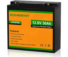
Does you battery have 4 separate wires like you show?
Your load (arduino/pump) should be connected to the Load output on the MPPT. Make sense?
i was recommended(chatgpt) to use EPever 10A 12V/24V MPPT Solar Charge Controller, but from the websites I looked at to understand a MPPT, the Victron's model was the most recurrent one. i am unsure of the programming.
I haven't used bus bars before, but I will try to understand them and redraw the diagram as well.
i was researching and the arduino uno is meant to be able to use 7-12v and can output 5, hence why i attached the 5v relay to the arduino power instead of the battery.
I take it the Arduino NANO Every has a 5v output as well?
the battery I put an example picture above, from what i can see it wouldn't have 4 terminals, but I will check into this.
as for the load, I think I understand
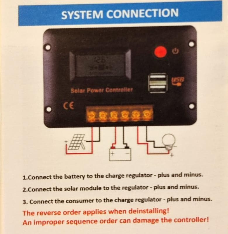
I take it you mean place it where the light bulb would be in this image?
if that's the case wouldn't that eliminate the purpose of the battery?
No. When you have sun the battery will be charged and the load will be powered by some combination of the solar panel and battery. When there is no sun, the load is powered by the battery only.
i get it, this is what trickle charging is right?
based of the wiring diagrams what would i need to change?
No, it is not. All batteries self discharge to some extent, when not connected to a charger or a load. Trickle charge matches the self discharge current so the battery is not depleted over time.
Trickle charging is just keeping an already fully charged battery fully charged. When there is no sun you may use up 50% of the battery capacity, so when there is sun you will be doing more that just trickling.
If you intend to use the LiFePO4 battery you need to find an MPPT that can charge that kind of battery.