In which file can I find the declaration of function pinMode() ?

Hi everybody,

I did search for the declaration of the function pinMode() for AVR-cores. But had no luck so far.

I guess that this function belongs to the core-files which are located in
C:\Users...\AppData\Local\Arduino15

But maybe I am wrong.
I did find this

void FirmataClass::attach(uint8_t command, ::callbackFunction newFunction)
{
  switch (command) {
    case ANALOG_MESSAGE:
      currentAnalogCallback = newFunction;
      break;
    case DIGITAL_MESSAGE:
      currentDigitalCallback = newFunction;
      break;
    case REPORT_ANALOG:
      currentReportAnalogCallback = newFunction;
      break;
    case REPORT_DIGITAL:
      currentReportDigitalCallback = newFunction;
      break;
    case SET_PIN_MODE:
      currentPinModeCallback = newFunction;
      break;
    case SET_DIGITAL_PIN_VALUE:
      currentPinValueCallback = newFunction;
      break;
  }
}

the function names have "callback" as part of the name.
Now I am puzzled.
I did expect to find a simple

void pinMode(......

but maybe I am completely wrong about that.

My final question I wanted to answer to myself by looking nto the source-code is:

If IDE is adjusted to Arduino-Uno (=AVR-core)
Das a function-call like
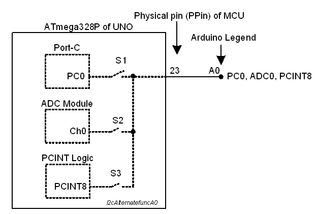
pinMode(A0, INPUT);

where A0 is the analog input.

configure the IO-pin as digital input? Or will the IO-pin still be reading in analog values?

This is in C:\Users\micro\AppData\Local\Arduino15\packages\arduino\hardware\avr\1.8.6\cores\arduino\wiring_digital.c on my PC

#define ARDUINO_MAIN
#include "wiring_private.h"
#include "pins_arduino.h"

void pinMode(uint8_t pin, uint8_t mode)
{
	uint8_t bit = digitalPinToBitMask(pin);
	uint8_t port = digitalPinToPort(pin);
	volatile uint8_t *reg, *out;

	if (port == NOT_A_PIN) return;

	// JWS: can I let the optimizer do this?
	reg = portModeRegister(port);
	out = portOutputRegister(port);

	if (mode == INPUT) { 
		uint8_t oldSREG = SREG;
                cli();
		*reg &= ~bit;
		*out &= ~bit;
		SREG = oldSREG;
	} else if (mode == INPUT_PULLUP) {
		uint8_t oldSREG = SREG;
                cli();
		*reg &= ~bit;
		*out |= bit;
		SREG = oldSREG;
	} else {
		uint8_t oldSREG = SREG;
                cli();
		*reg |= bit;
		SREG = oldSREG;
	}
}

an analogRead(A0) will still read the analog value.

You can test this on an UNO

void setup() {
  Serial.begin(115200);
  pinMode(A0, INPUT);  // not needed for analogRead
}

void loop() {
  Serial.println(analogRead(A0));
  delay(500); // dirty delay
}

Arduino analogRead() sets the pin to use the analog read feature. The pinMode() command only covers digital pin use, A0 to A5 on an Uno can be analog-in or digital.

I never checked but I don't think that analogRead() changes the 3 digital registers behind every AVR Port.

How this goes with non-AVR's.. I just dunno!

Hi @UKHeliBob,

Thank you very much for answering. Learned something new. Corefiles can have the extension *.c (instead of *.cpp) I guess this is the case if the files are pure "c" and no c++.

@noiasca

now that you have stated it. Yes seems to be clear. Different function-call using different internal hardware (ADC) should not be affected by a digial-input configuration

So thank you both for answering.

@GoForSmoke Yes can be different on different microcntrollers. I asked specific for Atmel AVR

SOME core files are C, some are C++.

IMO, It can be easier to look for source code at github:

It has search, and a source-browser...

1 Like

1. A0, A1, A2, A3, A4, A5 are just printed legends near the edge connector of the Arduino UNO Board. They are uttered, by many of the users, as A0-pin, A1-pin etc.

2. The A0-pin is connected by PCB track with PPin-23 (Physical Pin-23, Fig-1) of ATmega328P MCU of the UNO Board. PPin-23 is associated with following signals which come into action one at a time.

PC0(ADC0/PCINT8)


Figure-1:

3. By default, PPin-23 is a digital IO line. It will send 1-bit data to outside device or will receive 1-bit data from outside device. At this time, the name PC0 (Bit-0 of Port-C Register) has been given to PPin-23 in the data sheets (Fig-2).

4. In Arduino IDE Programming environment, the digital IO pin of Step-3 has been given the name A0/14 which the Smart Compiler maps into appropriate assembly/machine codes that are suitable suitable for the MCU to execute. The following codes are valid:

pinMode(A0, INPUT);
int pinValue = digitalRead(A0);

5. PPin-23 gets connected with Ch-0 of the internal ADC of the MCU when the following code is included in the sketch. At this time, the name ADC0(Ch-0 of ADC) has been given to PPin-23 in the data sheets (Fig-2).

bitSet(ADCSRA, ADEN);

Now the PPin-23 acquires analog signal from an external sensor whose output is connected with A0-pin of the edge connector. The following codes are valid in the IDE programming Env.

int y = analogRead(A0);  //

6. PPin-23 gets connected with Pin Change Interrupt Logic of the MCU when the following code is included in the sketch. At this time, the name PCINT8 (Pin Change Interrupt of Type-8) has been given to PPin-23 in the data sheets (Fig-2).

bitSet(PCICR, PCIE1);

Now the PPin-23 detects any logic level change on it imposed by an external device and then enters into the relevant Interrupt Sub Routine.

7. The following diagram (Fig-2) is an attempt to present the alternate functions of PPin-23 of the ATmega328P MCU.


Figure-2:

My go-to trick is to look for them on github as a two step process:

https://www.google.com/search?q=github+arduino+core

...then in the github repository, look for the "pinmode" keyword:

which has links to the source:

Also, github has a pretty nice contextual search tool on the RHS. If you click on "NOT_A_PIN" it can lead to suggestion to find to its definition.

Using the Eclipse / Sloeber IDE, I Right Click on the function call in my code and select "Open Declaration" from the popup context menu. That opens the associated source file from the Board Core, a library, or another file in the same project. It will locate both header and implementation files. It works 95+% of the time. There is some flakiness with heavily-templated code but you still get a general idea. I understand that Arduino IDE 2.x has a similar feature.

1 Like

Yes, in IDE 2.x, you can sometimes get it "early". You may have to wait while it says "Building sketch" or "Indexing" in the lower left corner. But definitely after Verify/Upload/compile, if that is successful: you can hover over the name with the mouse pointer

void setup() {
  // put your setup code here, to run once:
  pinMode(A0, INPUT);
}

void loop() {
  // put your main code here, to run repeatedly:

}

and you should see an info box

function pinMode
→ void
Parameters:

uint8_t pin
uint8_t mode
void pinMode(uint8_t pin, uint8_t mode)

Then if you right-click you can choose Go to Definition in the menu (there's also an OS-specific keyboard shortcut), and it will take you to the file, wiring_digital.c in this case.

Hovering over the file tab will show you the full path. Depending on the OS, you may be able to copy the text of that path to do something with it.

1 Like

This topic was automatically closed 180 days after the last reply. New replies are no longer allowed.