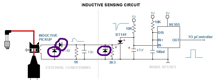
In this circuit, only the 1N4148 diode is named. Can anyone tell me what the other two diodes might be please?

I see only one other diode. Google will tell you about the BT149.
Paul
Google will tell you about the BT149.
Or, if you knew schematic symbols, you would know it is an SCR.
In this circuit, only the 1N4148 diode is named.
No
In this circuit, only the two 1N4148 diodes are named. The other one can also be a 1N4148.
The other diode (placed in parallel with 3K3 resistor) most likely is a zener diode to limit a gate voltage.
Wow! Thank you all for your contributions.
To summarise:
- I can assume that the naming of 1N4148 applies to both of the diodes in the vicinity of it;
- The diode across the 3k3 resistor can be also 1N4148, but would be better as a zener, even though it is not shown with the usual zener image;
- Confirming my basic knowledge that the BT149 is an SCR.
In the interest of completeness, the source of the schematic, something that the OP should have provided. The reason for the red asterisks explained.
I'm sorry about that. I didn't understand the signifigance of the asterisks, and frankly, I still don't.
lodgernz:
I'm sorry about that. I didn't understand the signifigance of the asterisks, and frankly, I still don't.
An asterisk against a component often means “read the notes associated with this diagram”.
And then there's the asreisked asterisk which means "Read the Notes associated with the Notes
Associated with this diagram"...
True! There are three diodes there. And only 1 diode label. So assumptions need to be made. And then make sure we add a note to say that somebody forgot to label all the diodes 'properly'.
lodgernz:
I'm sorry about that. I didn't understand the signifigance of the asterisks, and frankly, I still don't.
The asterisks are to indicate that the components are changes to the previous design.
https://www.sportdevices.com/rpm_readings.php