I was reading over the internet how to create a acceptable power meter during this searching I only found some circuits but those doesn't have all the parameters i have to use to my proyect, and the error of those circuits was unpredictable. The parameters I was looking for are:
Voltage, Current, THD, Individual Harmonic Analisis, Ractive Power and Power Factor. All values for Three Phase system.
The best idea of power metering using simple electronic elements and one arduino used for process the signals was openenergymonitor.org, (EMON). But i was never capable to calibrate it the error in Power Factor was terrible for small currents.
My next idea was using an industrial meter but, how to comunicate this to my Arduino?. The used Modbus protocol with a library called Simple-Modbus-Master and Simple-Modbus-Slave and it was very usefull but i only used this for communicate arduinos.
Looking around the internet I Found An interesting power meter, The Acuvim-L And I bought one the Acuvim-DL vercion, there are many version the diference is the parameters it reads, but all of then has modbus protocol.
In the beginning of the tests of communicate with my arduino, I was having some troubles but the power meter has an icon that indicate that the comminication is ok and it was online. But i didnt have any response in the arduino, The problem was the timing between the byte sending. So I used a low baundrate.
Here is the code I used in the Arduino, In This case the Master Modbus point.
#include <SimpleModbusMaster.h>
#include <SoftwareSerial.h>
#include <SimpleTimer.h>SoftwareSerial mySerial(10, 11); // RX, TX
SimpleTimer timer;//////////////////// Port information ///////////////////
#define baud 9600
#define timeout 1000
#define polling 200 // the scan rate// If the packets internal retry register matches
// the set retry count then communication is stopped
// on that packet. To re-enable the packet you must
// set the "connection" variable to true.
#define retry_count 10// used to toggle the receive/transmit pin on the driver
#define TxEnablePin 2#define LED 9
// This is the easiest way to create new packets
// Add as many as you want. TOTAL_NO_OF_PACKETS
// is automatically updated.
enum
{
PACKET1,
PACKET2,
PACKET3,
PACKET4,
PACKET5,
PACKET6,
PACKET7,
TOTAL_NO_OF_PACKETS // leave this last entry
};// Create an array of Packets to be configured
Packet packets[TOTAL_NO_OF_PACKETS];
packetPointer packet1 = &packets[PACKET1];
packetPointer packet2 = &packets[PACKET2];
packetPointer packet3 = &packets[PACKET3];
packetPointer packet4 = &packets[PACKET4];
packetPointer packet5 = &packets[PACKET5];
packetPointer packet6 = &packets[PACKET6];
packetPointer packet7 = &packets[PACKET7];
// Data read from the arduino slave will be stored in this array
// if the array is initialized to the packet.
unsigned int cont=0;
unsigned int control=2050;
unsigned int readRegs[2];
unsigned int readRegs1[1];
unsigned int readRegs2[6];
unsigned int AV1[5];
unsigned int AV2[5];
unsigned int AV3[5];
unsigned int VFloat[2];void setup()
{
mySerial.begin(9600);timer.setInterval(2000, RepeatTask);
modbus_construct(packet1, 17, READ_HOLDING_REGISTERS, 0x130, 2, readRegs);modbus_construct(packet2, 17, READ_HOLDING_REGISTERS, 0x400, 1, readRegs1);
modbus_construct(packet3, 17, READ_HOLDING_REGISTERS, 0x184, 6, readRegs2);
modbus_construct(packet4, 17, READ_HOLDING_REGISTERS, 0x406, 5, AV1);
modbus_construct(packet5, 17, READ_HOLDING_REGISTERS, 0x40B, 5, AV2);
modbus_construct(packet6, 17, READ_HOLDING_REGISTERS, 0x410, 5, AV3);modbus_configure(&Serial, baud, SERIAL_8N2, timeout, polling, retry_count, TxEnablePin, packets, TOTAL_NO_OF_PACKETS);
pinMode(LED, OUTPUT);
}void loop()
{
modbus_update();
timer.run();
}void RepeatTask() {
//fecha
mySerial.print(int(readRegs2[0]));mySerial.print("/"); //año
mySerial.print(int(readRegs2[1]));mySerial.print("/"); //mes
mySerial.print(int(readRegs2[2]));mySerial.print(" "); //dia
mySerial.print(int(readRegs2[3]));mySerial.print(":"); //hora
mySerial.print(int(readRegs2[4]));mySerial.print(":"); //minuto
mySerial.println(int(readRegs2[5]));
//mySerial.println(int(readRegs2[6])); //semana
mySerial.print("F=");
mySerial.print(float(readRegs[0])/100);
mySerial.print(" ");
mySerial.print("V1=");
mySerial.println(float(readRegs[1])/10);
mySerial.print("THD1=");
mySerial.print(float(readRegs1[0])/100);
mySerial.println(" ");
mySerial.println("Contenido Armonico Voltage");
mySerial.print("% V2=");mySerial.print(float(AV1[0])/100);
mySerial.print(" % V3=");mySerial.print(float(AV1[1])/100);
mySerial.print(" % V4=");mySerial.print(float(AV1[2])/100);
mySerial.print(" % V5=");mySerial.print(float(AV1[3])/100);
mySerial.print(" % V6=");mySerial.println(float(AV1[4])/100);
mySerial.print("% V7=");mySerial.print(float(AV2[0])/100);
mySerial.print(" % V8=");mySerial.print(float(AV2[1])/100);
mySerial.print(" % V9=");mySerial.print(float(AV2[2])/100);
mySerial.print(" % V10=");mySerial.print(float(AV2[3])/100);
mySerial.print(" % V11=");mySerial.println(float(AV2[4])/100);
mySerial.print("% V12=");mySerial.print(float(AV3[0])/100);
mySerial.print(" % V13=");mySerial.print(float(AV3[1])/100);
mySerial.print(" % V14=");mySerial.print(float(AV3[2])/100);
mySerial.print(" % V15=");mySerial.print(float(AV3[3])/100);
mySerial.print(" % V16=");mySerial.println(float(AV3[4])/100);
}
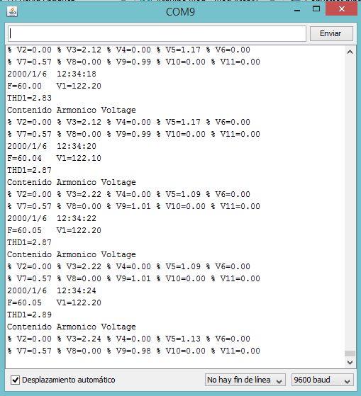
This code is for print some values from the Power meter, I used one softwareSerial port to show the results because the hardware Serial is used to the modbus RS485 adapter just a simple MAX485.
The schematic is this:
The only difference between this schematic and my project is that I used one MAX485 Module http://yourduino.com/sunshop2/index.php?l=product_detail&p=323 the only thing you have to do is to plug it exactly the same pins of the max485. This is the schematic of this module, it only add the 120 resistor in the output and some other resistors and power protection also have one Indicator Led.

The last think you have to do is to plug A and B to the Communication Terminal Strips located in the Acuvim-L Module. There are also one S pin in the power meter, I didn't plug it anywhere. I thing S pin is for noise effects but it works in large Distance.
The SimpleTimer library is easy to find in the arduino library repository, I used this because the writing a "delay" in the loop() function caused something wrong in the communication seems like it is slow, but this library is great because it doesnt do anything in the loop function it just waits for the pass of the time and it opens the repeat task function.
Thats all I can say, if anyone is interested in more details to do it works I can share some more information, Is a good power meter it has a accuracy table
Here are some results of the comunication.

