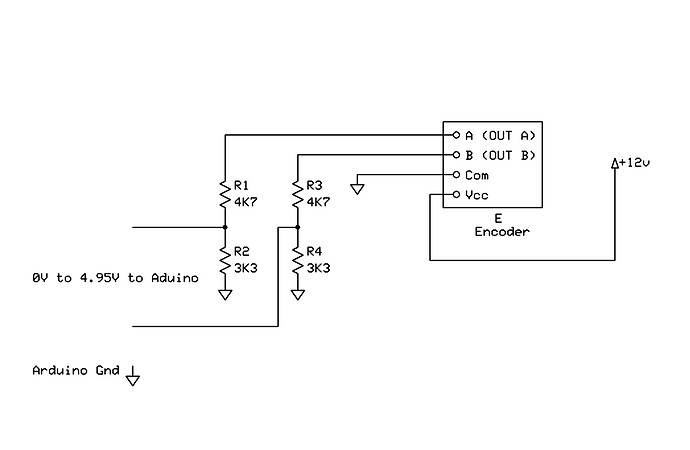
I'm trying to use a motor with an encoder and I'm having problems reading the signal. The voltage input for the encoder is 12V and I made a voltage divider and with the resistor I have, I have a voltage of 4.30V. That voltage would be enough for the signal for the arduino to read. Somehow works but is not very consistant.
Thanks
Thanks for letting us know.
Jacusan,
I would suggest that AWOL's typical passive-aggressive hostile post points out that your original post doesn't 1) actually ask a a question, 2) provide any details on the motor, encoder, or any of the components involved, and 3) doesn't provide anything like a schematic or a hook-up diagram.
I would further suggest adding this sort of information would increase the likelihood of you receiving a helpful or useful response that might lead you to resolving your issue.
Cheers
hi bigred1212,
I'm trying to read the encoder of this motor.
As you can read on the page the input voltage for the encoder is 7-24V. I'm using a 12v battery to supply the voltage but of course the 12v output signal is too high for the arduino. I asked arround and someone sugested a voltage divider to lower the voltage. I connected the resistors and now I have 4.30V connected to the arduino input.
I'm using the "switch" sketch from the library. The only change I add a print.line just to confirm I'm reading the encoder. Seems to work but is not constant. Seems to skip a bit (more than one actually) once in a while.
The question is. Is 4.30V enough for the arduino to read or should be closer to 5V?
/* switch
 *
 * Each time the input pin goes from LOW to HIGH (e.g. because of a push-button
 * press), the output pin is toggled from LOW to HIGH or HIGH to LOW.  There's
 * a minimum delay between toggles to debounce the circuit (i.e. to ignore
 * noise).
 *
 * David A. Mellis
 * 21 November 2006
 */

int inPin = 34;         // the number of the input pin
int outPin = 13;       // the number of the output pin

int state = HIGH;      // the current state of the output pin
int reading;           // the current reading from the input pin
int previous = LOW;    // the previous reading from the input pin

// the follow variables are long's because the time, measured in miliseconds,
// will quickly become a bigger number than can be stored in an int.
long time = 0;         // the last time the output pin was toggled
long debounce = 200;   // the debounce time, increase if the output flickers

void setup()
{


  Serial.begin(9600);      // open the serial port at 9600 bps:


  pinMode(inPin, INPUT);
  pinMode(outPin, OUTPUT);
}

void loop()
{
  reading = digitalRead(inPin);

  // if the input just went from LOW and HIGH and we've waited long enough
  // to ignore any noise on the circuit, toggle the output pin and remember
  // the time
  if (reading == HIGH && previous == LOW && millis() - time > debounce) {
    if (state == HIGH)
      state = LOW;


    else
      state = HIGH;
Serial.print("I");
    time = millis();
  }

  digitalWrite(outPin, state);

  previous = reading;
}
What are the values of your resistor divider? If you've chosen very high values you might not be getting the signal at the input pin you think you are.
You have a linear actuator, not a simple DC motor. The encoder has two encoder outputs (green, white) usually named A and B channel. Debouncing seems not necessary, it will limit the signal frequency.
I hope that the motor has separate power lines?
Without further details given you should check the output of your voltage divider, in both HIGH and LOW state. Eventually a diode (cathode towards encoder) and pullup resistor to your controller operating voltage (5V?) yields better signal conditioning.
At the listed price I had expected a much more detailied data sheet and application notes.
This might be interesting:
"Using a voltage divider as a power source for almost anything is a Very Bad Idea. The actual voltage supplied to the load will vary with the load current. I expect that the current drawn by an Arduino will be Much, Much Greater than is drawn by your 10 meg resistor, so the voltage will be much less than you expect.
You should use a DC-DC converter (AKA switching regulator) to drop the 12 volts down to 5 for the logic. A linear regulator such as the LM7805 could also be used, if the 5 volt current demand is low, but a linear regulator will waste the excess power as heat."
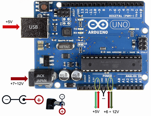
"The standard arduino boards ( ng, uno, duo, micro ) have a built-in regulator to which you can connect the 12V."
From https://www.open-electronics.org/the-power-of-arduino-this-unknown/ :
Personally, I would use separate power supplies for the board and the actuator.
bigred1212:
I would suggest that AWOL's typical passive-aggressive hostile post
Neither passive, nor aggressive; sarcastic,maybe, but simply a gentle prod to provide more detail.
AWOL's typical passive-aggressive hostile post
Why you fail to see the humor in the post, and characterize it so negatively?
Hi;
Can you please post a copy of your circuit, in CAD or a picture of a hand drawn circuit in jpg, png?
You should be using a potential divider on each of the encoder outputs and leaving 12V connected to the RED wire.
If you are supplying a potential divided voltage to the RED you will have problems, as the RED must have 7V to 12V to operate, this voltage needs to be a regulated supply.
If you google arduino encoder it will direct you to some libraries that will do what you want.
https://playground.arduino.cc/Main/RotaryEncoders
Tom.... ![]()

