For a school project, I have to control a NPN transistor with my Arduino to open the electric circuit between a sensor and a control unit
It's very easy, I just have to power off the base with my GPIO and the sensor will not communicate anymore with my control unit.
But I don't have many free space for my embedded system, so I can't put a breadboard with all the transistors next to my Arduino.
Do you know if there is a component looking like my schema in attachment ? It would be great if I can plug an integrated transistor directly in my GPIO's Arduino, and I could connect my sensor and my control unit to this 2 new "GPIOs".
If I only use one GPIO of the Arduino, why I just can't have one wire ?
I'm sorry, I don't completely understand your sentence (I am new with Arduino).
Thank you for your answer by the way.
arduin_ologist:
Because electricity needs a circuit; what you have is one hand clapping.
Expression Arduino_ologist used holds true. Picture you uploaded is a “concept” sadly it will not work as you need to provide GND to emitter, base voltage you use to turn the transistor is in respect to emitter e.g. base 0.7 V above emitter. So, you need to connect GPIO to base and GND to emitter.
Oh I see, so it will not work.
Thank you both of you for your answers.
Do you have an idea of what type of technology I can use for my project ?
I just need to open the wire between my sensor and my control unit, like a toggle switch.
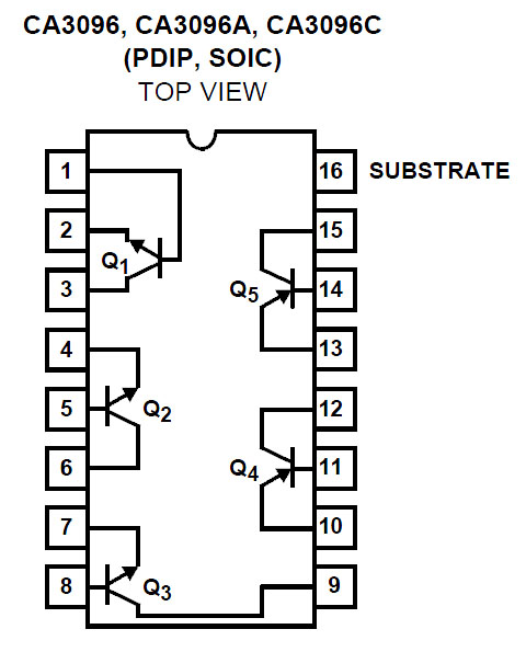
I found a transistor array, what do you think about this (schema in attachment) ? For example, if I connect my GPIO on pin n°1, my control unit on pin n°2 and my sensor on pin n°3, will it work or there is the same problem of GND ?
Unfortunately you will run in to same problem as this chip is like 4 transistors pack together and their individual operation is same. Picture attached shows how BJT pnp operates. I highlighted problem you will experience with red arrow. You need to have positive base voltage in respect to emitter to have collector emitter current.
what is the voltage and current of such a sensor, since you could feed the sensor with the 5v of arduino and the negative of the sensor connect to a pin in output, when the pin is low its sink current will turn on the sensor, remembering that for it is possible to use such a method the sensor must be fed with 5v and have a current below 40ma
The power supply of this sensor (24V DC) doesn't belong to me, I just have to do something with the wire of the output voltage which varies between 0.5V and 4.5V with a current of approximately 15mA (not enough to put a relay you see).
Yes of course, I found the D31B3100 from Celduc, its nominal input is 5V and its max switching current is 500mA (I may have some equipments to switch off also)
be careful when working with inductive loads such as relays and electromagnets because they tend to maintain the current that circulates even after the power voltage has been removed, thus generating a high destructive voltage at the terminals, to protect the circuit using an antiparallel diode with the relay coil, there are good small transistors for 24v be bjt or mosfet in smd, just search for "transistor" on the web with the voltage and current characteristics needed.
Yes you're right, the D31B3110 reed relay from Celduc has an antiparallel diode with the relay coil.
I looked for a transistor but it doesn't fit with my project (look at the messages above).
The problem with that reed-relay is that is doesn't have a schottky diode across it, so it may end
up dumping some/most/all of its free-wheel current into the Arduino pin's protection diode instead
which being small will likely have a lower forward voltage than the one in the relay unit.
Always use a schottky free-wheel diode with CMOS pins driving inductive loads so that the anti-static
protection diode in the CMOS device isn't put until strain (they are often rated at mA or less).