Cela t'indique qu'il y a un soucis sur une accolade fermante qui aurait dû être positionné quelque part avant la ligne indiqué.
il faut mettre tout le message d'erreur, c'est possible qu'il y ait d'autre indication avant ce message.
Il ne faut pas mettre d'image de texte, cela n'a aucune interret et c'est clairement indiqué dans les bonnes pratiques
Ton code n'est pas indenté, l'indatation permet de repéré facilement ce type d'erreur.
dans l'IDE d'Arduino, cela se fait avec un Ctr+T.
voici le code erreur complet :
C:\Users\nico-\AppData\Local\Temp\arduino\sketches\D1D789B9DF4ED8165AA1E660CAEDBFAC\sketch\Joystick.cpp.o (symbol from plugin): In function `setup':
(.text+0x0): multiple definition of `setup'
C:\Users\nico-\AppData\Local\Temp\arduino\sketches\D1D789B9DF4ED8165AA1E660CAEDBFAC\sketch\ARDUINO_BUTTON_BOXV2.ino.cpp.o (symbol from plugin):(.text+0x0): first defined here
C:\Users\nico-\AppData\Local\Temp\arduino\sketches\D1D789B9DF4ED8165AA1E660CAEDBFAC\sketch\Joystick.cpp.o (symbol from plugin): In function `setup':
(.text+0x0): multiple definition of `loop'
C:\Users\nico-\AppData\Local\Temp\arduino\sketches\D1D789B9DF4ED8165AA1E660CAEDBFAC\sketch\ARDUINO_BUTTON_BOXV2.ino.cpp.o (symbol from plugin):(.text+0x0): first defined here
collect2.exe: error: ld returned 1 exit status

exit status 1

Compilation error: exit status 1
je reprends, post #3 tu dis
suit un joli dessin ( avec un joystick en haut à droite)
puis sous ce joli dessin:
"le code que j'utilise sur la micro"
suit un code.
jusque là, c'est clair, on pense que le dessin correspond au code.
mais post #4, tu dis:
sous entendu le code du post #3
suit un nouveau joli dessin ( sans joystick )
désolé mais pas claire ton histoire, peux tu reprendre tes explications
effectivement je me suis peut-être mal exprimé concernant mon branchement...
J'ai simplement utilisé le même code que pour l'arduino micro Pro et je l'ai téleversé dans une micro (plus grosse) en changeant juste quelques entrées pin pour que ça corresponde à mon branchement.
Donc aujourd'hui c'est branché comme ceci :
et il me faut tout simplement une intégration ou modification du code pour y intégrer le joystick branché en A5, A4 et 13...
C'est pourtant simple apparemment mais personne n'y arrive !!!
hello
mise au point:
sur le forum, il y a de très nombreuses personnes qui savent le faire, mais tel que tu présentais le problème, c'était trop brouillon .
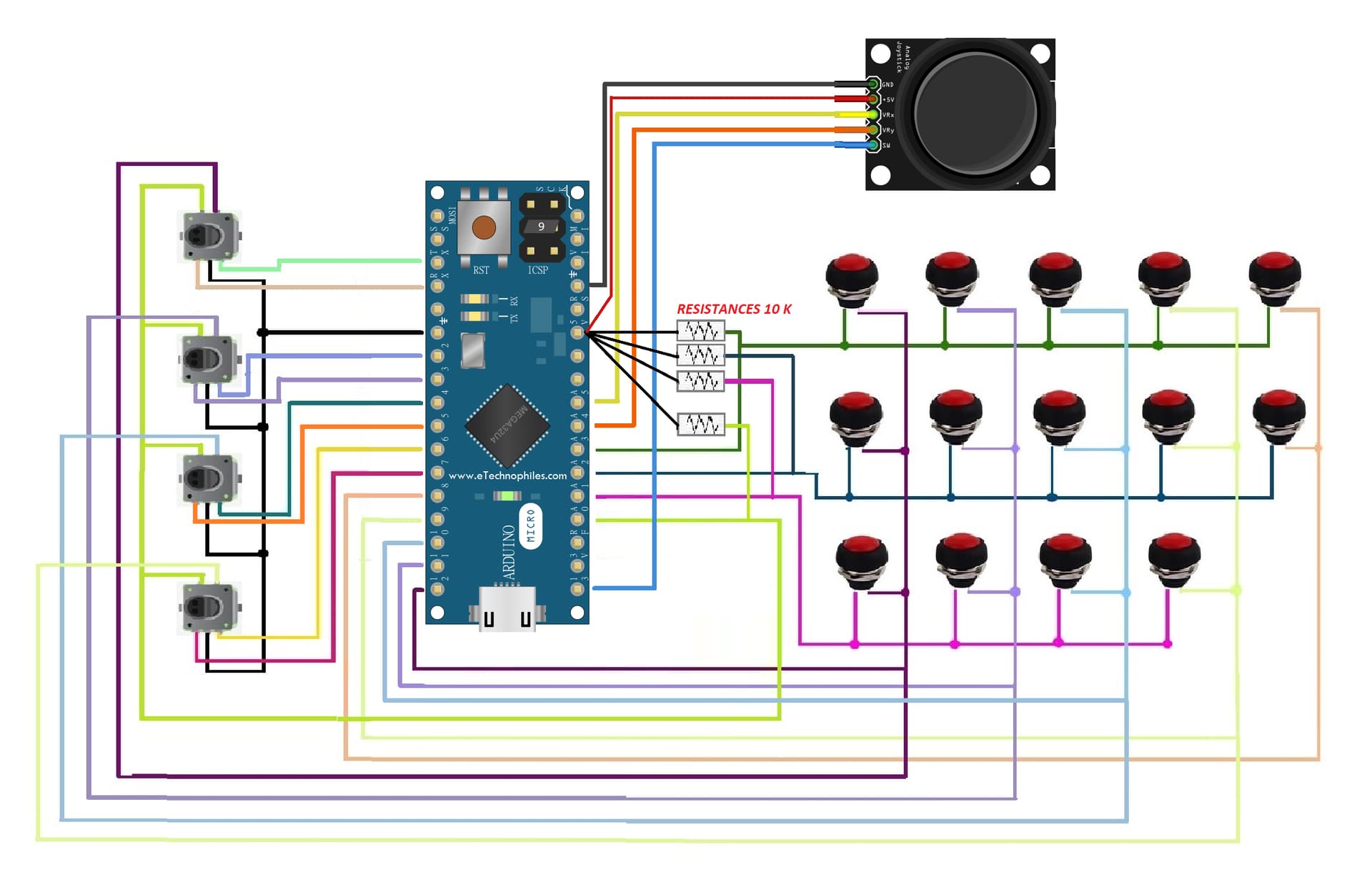
j'avais déjà imprimé ton code et tes 2 images .
j'avais corrigé les affectations des entrées ( exemple le switch de ton joystick était sur le schéma sur D12 ).
![]()
maintenant tu ré-édites le dessin de ton cablage, et le switch est sur D13.
mais sur d13, il y avait Colonne 1 de ton clavier de BP......... et peut etre d'autres modifs).
le but pour moi était de pouvoir compiler ton prg, et pour cela, n'ayant pas trouvé la librairie "Joystick" que tu utilises , j'ai neutralisé toutes les lignes se rapportant à joystick.
ceci étant fait, ton prog compile.
j'ai ensuite intégré une fonction "init_joystick()" et une fonction "lecture_joystick()".
en utilisant le bout de code que tu as joint dans ton post.
la compilation se passe bien.
si le fonctionnement n'est pas celui que tu attends, penses à vérifier tes affectations de pins
et puis, tu peux toujours revenir nous dire si tout va bien
voici ton code
//BUTTON BOX
//USE w ProMicro
//Tested in WIN10 + Assetto Corsa
//AMSTUDIO
//20.8.17

#include <Keypad.h>
//#include <Joystick.h>

#define ENABLE_PULLUPS  // flag pour init des entrées en PULLUP selon le hard
#define NUMROTARIES 4   // nombre d'encodeurs
#define NUMBUTTONS 24   // nombre de boutons poussoir
#define NUMROWS 4       // nombre de lignes de la matrice de BP
#define NUMCOLS 5       // nombre de colonnes de la matrice de BP
//#define HALF_STEP     // décommenter pour etre en demi pas

byte buttons[NUMROWS][NUMCOLS] = {  //image du clavier formé par les BP et les switchs des encodeurs
  { 0,  1,  2,  3,  4},
  { 5,  6,  7,  8,  9},
  {10, 11, 12, 13 },
  {15, 16, 17, 18 }
};

struct rotariesdef {             // structures pour gerer les 4 encodeurs
  byte pin1;                     // pour structure 0: pin1    =  0  voie A entrée D0
  byte pin2;                     // pour structure 0: pin1    =  1  voie B entrée D1
  int ccwchar;                   // pour structure 0: ccwchar = 24  sens anti horaire
  int cwchar;                    // pour structure 0: cwchar  = 25  sens horaire
  volatile unsigned char state;  // pour structure 0: state   =  0  switch ?
};

rotariesdef rotaries[NUMROTARIES] {
  {0, 1, 24, 25, 0},  //init de la structure pour l'encodeur 0
  {2, 3, 26, 27, 0},  //init de la structure pour l'encodeur 1
  {4, 5, 28, 29, 0},  //init de la structure pour l'encodeur 2
  {6, 7, 30, 31, 0},  //init de la structure pour l'encodeur 3
};

#define DIR_CCW 0x10  //decimal=16  binaire = 0001 0000
#define DIR_CW  0x20  //decimal=32  binaire = 0010 0000
#define R_START 0x0   //decimal= 0  binaire = 0000 0000

#ifdef HALF_STEP

#define R_CCW_BEGIN   0x1
#define R_CW_BEGIN    0x2
#define R_START_M     0x3
#define R_CW_BEGIN_M  0x4
#define R_CCW_BEGIN_M 0x5
const unsigned char ttable[6][4] = {
  // R_START (00)
  {R_START_M,            R_CW_BEGIN,     R_CCW_BEGIN,  R_START},
  // R_CCW_BEGIN
  {R_START_M | DIR_CCW, R_START,        R_CCW_BEGIN,  R_START},
  // R_CW_BEGIN
  {R_START_M | DIR_CW,  R_CW_BEGIN,     R_START,      R_START},
  // R_START_M (11)
  {R_START_M,            R_CCW_BEGIN_M,  R_CW_BEGIN_M, R_START},
  // R_CW_BEGIN_M
  {R_START_M,            R_START_M,      R_CW_BEGIN_M, R_START | DIR_CW},
  // R_CCW_BEGIN_M
  {R_START_M,            R_CCW_BEGIN_M,  R_START_M,    R_START | DIR_CCW},
};

#else

#define R_CW_FINAL   0x1
#define R_CW_BEGIN   0x2
#define R_CW_NEXT    0x3
#define R_CCW_BEGIN  0x4
#define R_CCW_FINAL  0x5
#define R_CCW_NEXT   0x6

const unsigned char ttable[7][4] = {
  // R_START
  {R_START,    R_CW_BEGIN,  R_CCW_BEGIN, R_START},                     //0,2,4,0
  // R_CW_FINAL
  {R_CW_NEXT,  R_START,     R_CW_FINAL,  R_START | DIR_CW},            //3,0,1,0|20 dec 32 bit4
  // R_CW_BEGIN
  {R_CW_NEXT,  R_CW_BEGIN,  R_START,     R_START},                     //3,2,0,0
  // R_CW_NEXT
  {R_CW_NEXT,  R_CW_BEGIN,  R_CW_FINAL,  R_START},                     //3,2,1,0
  // R_CCW_BEGIN
  {R_CCW_NEXT, R_START,     R_CCW_BEGIN, R_START},                     //6,0,4,0
  // R_CCW_FINAL
  {R_CCW_NEXT, R_CCW_FINAL, R_START,     R_START | DIR_CCW},           //6,5,0,0|10 dec 16 bit3
  // R_CCW_NEXT
  {R_CCW_NEXT, R_CCW_FINAL, R_CCW_BEGIN, R_START},                     //6,5,4,0
};
#endif

//byte rowPins[NUMROWS] = {21, 20, 19, 18, 15};
byte rowPins[NUMROWS] = {A3, A2, A1, A0};   //nombre de lignes de la matrice des BP en clavier
//byte colPins[NUMCOLS] = {14, 16, 10, 9, 8};
byte colPins[NUMCOLS] = {13, 11, 10, 9, 8}; //nombre de colonnes de la matrice des BP en clavier

Keypad buttbx = Keypad( makeKeymap(buttons), rowPins, colPins, NUMROWS, NUMCOLS);
//Joystick_ Joystick(JOYSTICK_DEFAULT_REPORT_ID,
//                  JOYSTICK_TYPE_JOYSTICK, 32, 0,
//                   false, false, false, false, false, false,
//                   false, false, false, false, false);

const int SW_pin = 12; // digital pin connected to switch output // à adapter
const int X_pin = A5; // analog pin connected to X output // à adapter
const int Y_pin = A4; // analog pin connected to Y output // à adapter

void setup() {
  Serial.begin(115200);
  //  Joystick.begin();
  rotary_init();
  init_joystick();
}

void loop() {
  CheckAllEncoders();
  CheckAllButtons();
  lecture_joystick();
}

unsigned char rotary_process(int _i)
{ if (_i == 1) {
    Serial.print(F("digitalRead(rotaries[_i].pin2 = "));
    Serial.println(digitalRead(rotaries[_i].pin2));
  }
  unsigned char pinstate = (digitalRead(rotaries[_i].pin2) << 1) | digitalRead(rotaries[_i].pin1);
  if (_i == 10) {
    Serial.print(F("pinstate = "));
    Serial.println(pinstate);
  }
  rotaries[_i].state = ttable[rotaries[_i].state & 0xf][pinstate];
  if (_i == 10) {
    Serial.print(F("rotaries[_i].state = "));
    Serial.println(rotaries[_i].state);
  }
  if (_i == 10) {
    Serial.print(F("rotaries[_i].state = "));
    Serial.println((rotaries[_i].state) & 0x30);
  }
  return (rotaries[_i].state & 0x30);//retourne 0x32 si horaire et 0x16 si anti-horaire
}

void CheckAllEncoders(void)
{
  for (int i = 0; i < NUMROTARIES; i++) {
    unsigned char result = rotary_process(i);
    if (result == DIR_CCW) {
      Serial.print(F("anti horaire encodeur N° ")); Serial.print (i); Serial.print(F("  ")); Serial.println(result);
      // Joystick.setButton(rotaries[i].ccwchar, 1); delay(50); Joystick.setButton(rotaries[i].ccwchar, 0);
    }
    if (result == DIR_CW) {
      Serial.print(F("horaire encodeur N° ")); Serial.print (i); Serial.print(F("  ")); Serial.println(result);
      // Joystick.setButton(rotaries[i].cwchar, 1); delay(50); Joystick.setButton(rotaries[i].cwchar, 0);
    }
  }
}
//pour tous les encodeurs
//retour horaire = 32
//retour anti horaire = 16

void rotary_init()
{
  for (int i = 0; i < NUMROTARIES; i++)    // initialise les entrées sur lesquelles sont raccordées
  {
    pinMode(rotaries[i].pin1, INPUT);     // les voies A et B des encodeurs comme des entrées
    pinMode(rotaries[i].pin2, INPUT);     // et selon le hard
#ifdef ENABLE_PULLUPS                     // il est possible de définir "ENABLE_PULLUP"
    digitalWrite(rotaries[i].pin1, HIGH); // afin d'activer les résistances de PULLUP
    digitalWrite(rotaries[i].pin2, HIGH);
#endif
  }
}
void CheckAllButtons(void)
{
  if (buttbx.getKeys())
  {
    for (int i = 0; i < LIST_MAX; i++)
    {
      if ( buttbx.key[i].stateChanged )
      {
        switch (buttbx.key[i].kstate)
        {
          case PRESSED:
          case HOLD:
            //            Joystick.setButton(buttbx.key[i].kchar, 1);
            break;
          case RELEASED:
          case IDLE:
            //            Joystick.setButton(buttbx.key[i].kchar, 0);
            break;
        }
      }
    }
  }
}

void init_joystick()
{
  pinMode(SW_pin, INPUT); //pin  BP du joystick passe en entrée
  digitalWrite(SW_pin, HIGH); //activation de la résistance de pullup
}


void lecture_joystick()
{
  int XValue = analogRead(X_pin); // Read the analog value from the joystick X-axis
  int YValue = analogRead(Y_pin); // Read the analog value from the joystick Y-axis
  int SwValue = digitalRead(SW_pin); // Read the digital value from the joystick button
  Serial.print(F("axe X = ")); Serial.println(XValue);
  Serial.print(F("axe Y = ")); Serial.println(YValue);
  Serial.print(F("switch= ")); Serial.println(SwValue);
}
Ah mais effectivement , entre le premier et le deuxième schéma j'avais fais une modification de branchement du switch, qui est bien comme sur ce dernier du coup !
Je trouvais plus logique de brancher mes 5 colonnes à la suite de D8 à D12, et ensuite le SW du joystick sur D13...
Merci pour tes réponses, je vais essayer de voir ce que ça donne de mon côté ![]()
Alors de mon côté le programme compile bien également, mais maintenant je n'ai plus aucunes fonctions... j'ai vérifié les pins associées mais rien n'y fais...
tu as controlé les affectations des pins ? correspondent elles bien à ton hard?
tu as viré les Serial.print que j'ai mis ?
tu as viré les // que j'ai mis devant tout ce qui concerne "joystick" d'origine dans ton programme ?
si tout ça est ok, il n'y a pas de raison que le programme ne fonctionne pas.
je n'ai rien modifié, juste rajouté une branche qui est appelée dans la loupe.
si tu as encore un prob, il faudra nous remettre ton code
Voilà, je viens d'essayer de faire ce que tu m'a noté juste au dessus, mais impossible de faire fonctionner la boite !
On dirait qu'il manque une "activation" quelque part... je n'ai aucun boutons poussoirs ni aucun encodeurs qui fonctionne...
Voici le code que j'ai téléversé :
//BUTTON BOX
//USE w ProMicro
//Tested in WIN10 + Assetto Corsa
//AMSTUDIO
//20.8.17

#include <Keypad.h>
#include <Joystick.h>

#define ENABLE_PULLUPS  // flag pour init des entrées en PULLUP selon le hard
#define NUMROTARIES 4   // nombre d'encodeurs
#define NUMBUTTONS 24   // nombre de boutons poussoir
#define NUMROWS 5       // nombre de lignes de la matrice de BP
#define NUMCOLS 5       // nombre de colonnes de la matrice de BP
#define HALF_STEP     // décommenter pour etre en demi pas

byte buttons[NUMROWS][NUMCOLS] = {  //image du clavier formé par les BP et les switchs des encodeurs
  {0,1,2,3,4},
  {5,6,7,8,9},
  {10,11,12,13,14},
  {15,16,17,18,19},
};

struct rotariesdef {             // structures pour gerer les 4 encodeurs
  byte pin1;                     // pour structure 0: pin1    =  0  voie A entrée D0
  byte pin2;                     // pour structure 0: pin1    =  1  voie B entrée D1
  int ccwchar;                   // pour structure 0: ccwchar = 24  sens anti horaire
  int cwchar;                    // pour structure 0: cwchar  = 25  sens horaire
  volatile unsigned char state;  // pour structure 0: state   =  0  switch ?
};

rotariesdef rotaries[NUMROTARIES] {
  {0,1,24,25,0},
  {2,3,26,27,0},
  {4,5,28,29,0},
  {6,7,30,31,0},
};

#define DIR_CCW 0x10  //decimal=16  binaire = 0001 0000
#define DIR_CW  0x20  //decimal=32  binaire = 0010 0000
#define R_START 0x0   //decimal= 0  binaire = 0000 0000

#ifdef HALF_STEP
#define R_CCW_BEGIN   0x1
#define R_CW_BEGIN    0x2
#define R_START_M     0x3
#define R_CW_BEGIN_M  0x4
#define R_CCW_BEGIN_M 0x5
const unsigned char ttable[6][4] = {
  // R_START (00)
  {R_START_M,            R_CW_BEGIN,     R_CCW_BEGIN,  R_START},
  // R_CCW_BEGIN
  {R_START_M | DIR_CCW, R_START,        R_CCW_BEGIN,  R_START},
  // R_CW_BEGIN
  {R_START_M | DIR_CW,  R_CW_BEGIN,     R_START,      R_START},
  // R_START_M (11)
  {R_START_M,            R_CCW_BEGIN_M,  R_CW_BEGIN_M, R_START},
  // R_CW_BEGIN_M
  {R_START_M,            R_START_M,      R_CW_BEGIN_M, R_START | DIR_CW},
  // R_CCW_BEGIN_M
  {R_START_M,            R_CCW_BEGIN_M,  R_START_M,    R_START | DIR_CCW},
};

#else

#define R_CW_FINAL   0x1
#define R_CW_BEGIN   0x2
#define R_CW_NEXT    0x3
#define R_CCW_BEGIN  0x4
#define R_CCW_FINAL  0x5
#define R_CCW_NEXT   0x6

const unsigned char ttable[7][4] = {
  // R_START
  {R_START,    R_CW_BEGIN,  R_CCW_BEGIN, R_START},                     //0,2,4,0
  // R_CW_FINAL
  {R_CW_NEXT,  R_START,     R_CW_FINAL,  R_START | DIR_CW},            //3,0,1,0|20 dec 32 bit4
  // R_CW_BEGIN
  {R_CW_NEXT,  R_CW_BEGIN,  R_START,     R_START},                     //3,2,0,0
  // R_CW_NEXT
  {R_CW_NEXT,  R_CW_BEGIN,  R_CW_FINAL,  R_START},                     //3,2,1,0
  // R_CCW_BEGIN
  {R_CCW_NEXT, R_START,     R_CCW_BEGIN, R_START},                     //6,0,4,0
  // R_CCW_FINAL
  {R_CCW_NEXT, R_CCW_FINAL, R_START,     R_START | DIR_CCW},           //6,5,0,0|10 dec 16 bit3
  // R_CCW_NEXT
  {R_CCW_NEXT, R_CCW_FINAL, R_CCW_BEGIN, R_START},                     //6,5,4,0
};
#endif

//byte rowPins[NUMROWS] = {21, 20, 19, 18, 15};
byte rowPins[NUMROWS] = {A3, A2, A1, A0};   //nombre de lignes de la matrice des BP en clavier
//byte colPins[NUMCOLS] = {14, 16, 10, 9, 8};
byte colPins[NUMCOLS] = {12, 11, 10, 9, 8}; //nombre de colonnes de la matrice des BP en clavier

Keypad buttbx = Keypad( makeKeymap(buttons), rowPins, colPins, NUMROWS, NUMCOLS);

Joystick_ Joystick(JOYSTICK_DEFAULT_REPORT_ID,
                 JOYSTICK_TYPE_JOYSTICK, 32, 0,
                  false, false, false, false, false, false,
                  false, false, false, false, false);

const int SW_pin = 13; // digital pin connected to switch output // à adapter
const int X_pin = A5; // analog pin connected to X output // à adapter
const int Y_pin = A4; // analog pin connected to Y output // à adapter

void setup() {
  Serial.begin(115200);
  Joystick.begin();
  rotary_init();
  init_joystick();
}

void loop() {
  CheckAllEncoders();
  CheckAllButtons();
  lecture_joystick();
}

unsigned char rotary_process(int _i)
{ if (_i == 1) {
    Serial.print(F("digitalRead(rotaries[_i].pin2 = "));
    Serial.println(digitalRead(rotaries[_i].pin2));
  }
  unsigned char pinstate = (digitalRead(rotaries[_i].pin2) << 1) | digitalRead(rotaries[_i].pin1);
  if (_i == 10) {
    Serial.print(F("pinstate = "));
    Serial.println(pinstate);
  }
  rotaries[_i].state = ttable[rotaries[_i].state & 0xf][pinstate];
  if (_i == 10) {
    Serial.print(F("rotaries[_i].state = "));
    Serial.println(rotaries[_i].state);
  }
  if (_i == 10) {
    Serial.print(F("rotaries[_i].state = "));
    Serial.println((rotaries[_i].state) & 0x30);
  }
  return (rotaries[_i].state & 0x30);//retourne 0x32 si horaire et 0x16 si anti-horaire
}

void CheckAllEncoders(void)
{
  for (int i = 0; i < NUMROTARIES; i++) {
    unsigned char result = rotary_process(i);
    if (result == DIR_CCW) {
      Serial.print(F("anti horaire encodeur N° ")); Serial.print (i); Serial.print(F("  ")); Serial.println(result);
      // Joystick.setButton(rotaries[i].ccwchar, 1); delay(50); Joystick.setButton(rotaries[i].ccwchar, 0);
    }
    if (result == DIR_CW) {
      Serial.print(F("horaire encodeur N° ")); Serial.print (i); Serial.print(F("  ")); Serial.println(result);
      // Joystick.setButton(rotaries[i].cwchar, 1); delay(50); Joystick.setButton(rotaries[i].cwchar, 0);
    }
  }
}
//pour tous les encodeurs
//retour horaire = 32
//retour anti horaire = 16

void rotary_init()
{
  for (int i = 0; i < NUMROTARIES; i++)    // initialise les entrées sur lesquelles sont raccordées
  {
    pinMode(rotaries[i].pin1, INPUT);     // les voies A et B des encodeurs comme des entrées
    pinMode(rotaries[i].pin2, INPUT);     // et selon le hard
#ifdef ENABLE_PULLUPS                     // il est possible de définir "ENABLE_PULLUP"
    digitalWrite(rotaries[i].pin1, HIGH); // afin d'activer les résistances de PULLUP
    digitalWrite(rotaries[i].pin2, HIGH);
#endif
  }
}
void CheckAllButtons(void)
{
  if (buttbx.getKeys())
  {
    for (int i = 0; i < LIST_MAX; i++)
    {
      if ( buttbx.key[i].stateChanged )
      {
        switch (buttbx.key[i].kstate)
        {
          case PRESSED:
          case HOLD:
            //            Joystick.setButton(buttbx.key[i].kchar, 1);
            break;
          case RELEASED:
          case IDLE:
            //            Joystick.setButton(buttbx.key[i].kchar, 0);
            break;
        }
      }
    }
  }
}

void init_joystick()
{
  pinMode(SW_pin, INPUT); //pin  BP du joystick passe en entrée
  digitalWrite(SW_pin, HIGH); //activation de la résistance de pullup
}


void lecture_joystick()
{
  int XValue = analogRead(X_pin); // Read the analog value from the joystick X-axis
  int YValue = analogRead(Y_pin); // Read the analog value from the joystick Y-axis
  int SwValue = digitalRead(SW_pin); // Read the digital value from the joystick button
  Serial.print(F("axe X = ")); Serial.println(XValue);
  Serial.print(F("axe Y = ")); Serial.println(YValue);
  Serial.print(F("switch= ")); Serial.println(SwValue);
}
tu n'avais rien fait de ce que je t'avais demandé
j'ai récupéré ton code du # 3 que tu nous as dis fonctionner chez toi.
j'ai commenté tout ce qui avait trait à un joystick afin de pouvoir le compiler.
après avoir constaté qu'il compilait, j'ai rajouté les 2 fonctions pour ton joystick, et leurs appels dans le setup et dans la loop. sans oublier l'initialisation des pins faite juste au dessus du setup
j'ai vérifié qu'à ce stade, ton programme compilait bien. c'est le cas.
j'ai ensuite viré tous les commentaire que j'avais mis devant tes lignes de joystick.
à partir de là, je n'ai pas pu vérifier si la compilation se passait bien.
je te livre donc ton programme tel quel:
//BUTTON BOX
//USE w ProMicro
//Tested in WIN10 + Assetto Corsa
//AMSTUDIO
//20.8.17

#include <Keypad.h>
#include <Joystick.h>

#define ENABLE_PULLUPS
#define NUMROTARIES 4
#define NUMBUTTONS 24
#define NUMROWS 5
#define NUMCOLS 5


byte buttons[NUMROWS][NUMCOLS] = {
  {0, 1, 2, 3, 4},
  {5, 6, 7, 8, 9},
  {10, 11, 12, 13, 14},
  {15, 16, 17, 18, 19},
  {20, 21, 22, 23},
};

struct rotariesdef {
  byte pin1;
  byte pin2;
  int ccwchar;
  int cwchar;
  volatile unsigned char state;
};

rotariesdef rotaries[NUMROTARIES] {
  {0, 1, 24, 25, 0},
  {2, 3, 26, 27, 0},
  {4, 5, 28, 29, 0},
  {6, 7, 30, 31, 0},
};

#define DIR_CCW 0x10
#define DIR_CW 0x20
#define R_START 0x0

#ifdef HALF_STEP
#define R_CCW_BEGIN 0x1
#define R_CW_BEGIN 0x2
#define R_START_M 0x3
#define R_CW_BEGIN_M 0x4
#define R_CCW_BEGIN_M 0x5
const unsigned char ttable[6][4] = {
  // R_START (00)
  {R_START_M,            R_CW_BEGIN,     R_CCW_BEGIN,  R_START},
  // R_CCW_BEGIN
  {R_START_M | DIR_CCW, R_START,        R_CCW_BEGIN,  R_START},
  // R_CW_BEGIN
  {R_START_M | DIR_CW,  R_CW_BEGIN,     R_START,      R_START},
  // R_START_M (11)
  {R_START_M,            R_CCW_BEGIN_M,  R_CW_BEGIN_M, R_START},
  // R_CW_BEGIN_M
  {R_START_M,            R_START_M,      R_CW_BEGIN_M, R_START | DIR_CW},
  // R_CCW_BEGIN_M
  {R_START_M,            R_CCW_BEGIN_M,  R_START_M,    R_START | DIR_CCW},
};
#else
#define R_CW_FINAL 0x1
#define R_CW_BEGIN 0x2
#define R_CW_NEXT 0x3
#define R_CCW_BEGIN 0x4
#define R_CCW_FINAL 0x5
#define R_CCW_NEXT 0x6

const unsigned char ttable[7][4] = {
  // R_START
  {R_START,    R_CW_BEGIN,  R_CCW_BEGIN, R_START},
  // R_CW_FINAL
  {R_CW_NEXT,  R_START,     R_CW_FINAL,  R_START | DIR_CW},
  // R_CW_BEGIN
  {R_CW_NEXT,  R_CW_BEGIN,  R_START,     R_START},
  // R_CW_NEXT
  {R_CW_NEXT,  R_CW_BEGIN,  R_CW_FINAL,  R_START},
  // R_CCW_BEGIN
  {R_CCW_NEXT, R_START,     R_CCW_BEGIN, R_START},
  // R_CCW_FINAL
  {R_CCW_NEXT, R_CCW_FINAL, R_START,     R_START | DIR_CCW},
  // R_CCW_NEXT
  {R_CCW_NEXT, R_CCW_FINAL, R_CCW_BEGIN, R_START},
};
#endif

byte rowPins[NUMROWS] = {21, 20, 19, 18, 15};
byte colPins[NUMCOLS] = {14, 16, 10, 9, 8};

Keypad buttbx = Keypad( makeKeymap(buttons), rowPins, colPins, NUMROWS, NUMCOLS);

Joystick_ Joystick(JOYSTICK_DEFAULT_REPORT_ID,
                   JOYSTICK_TYPE_JOYSTICK, 32, 0,
                   false, false, false, false, false, false,
                   false, false, false, false, false);

const int SW_pin = 13; // digital pin connected to switch output // à adapter
const int X_pin = A5; // analog pin connected to X output // à adapter
const int Y_pin = A4; // analog pin connected to Y output // à adapter
void setup() {
  Joystick.begin();
  rotary_init();
  init_joystick();
}

void loop() {
  CheckAllEncoders();
  CheckAllButtons();
  lecture_joystick();
}

void CheckAllButtons(void) {
  if (buttbx.getKeys())
  {
    for (int i = 0; i < LIST_MAX; i++)
    {
      if ( buttbx.key[i].stateChanged )
      {
        switch (buttbx.key[i].kstate) {
          case PRESSED:
          case HOLD:
            Joystick.setButton(buttbx.key[i].kchar, 1);
            break;
          case RELEASED:
          case IDLE:
            Joystick.setButton(buttbx.key[i].kchar, 0);
            break;
        }
      }
    }
  }
}


void rotary_init() {
  for (int i = 0; i < NUMROTARIES; i++) {
    pinMode(rotaries[i].pin1, INPUT);
    pinMode(rotaries[i].pin2, INPUT);
#ifdef ENABLE_PULLUPS
    digitalWrite(rotaries[i].pin1, HIGH);
    digitalWrite(rotaries[i].pin2, HIGH);
#endif
  }
}


unsigned char rotary_process(int _i) {
  unsigned char pinstate = (digitalRead(rotaries[_i].pin2) << 1) | digitalRead(rotaries[_i].pin1);
  rotaries[_i].state = ttable[rotaries[_i].state & 0xf][pinstate];
  return (rotaries[_i].state & 0x30);
}

void CheckAllEncoders(void) {
  for (int i = 0; i < NUMROTARIES; i++) {
    unsigned char result = rotary_process(i);
    if (result == DIR_CCW) {
      Joystick.setButton(rotaries[i].ccwchar, 1); delay(50); Joystick.setButton(rotaries[i].ccwchar, 0);
    };
    if (result == DIR_CW) {
      Joystick.setButton(rotaries[i].cwchar, 1); delay(50); Joystick.setButton(rotaries[i].cwchar, 0);
    };
  }
}

void init_joystick()
{
  pinMode(SW_pin, INPUT); //pin  BP du joystick passe en entrée
  digitalWrite(SW_pin, HIGH); //activation de la résistance de pullup
}


void lecture_joystick()
{
  int XValue = analogRead(X_pin); // Read the analog value from the joystick X-axis
  int YValue = analogRead(Y_pin); // Read the analog value from the joystick Y-axis
  int SwValue = digitalRead(SW_pin); // Read the digital value from the joystick button
  Serial.print(F("axe X = ")); Serial.println(XValue);
  Serial.print(F("axe Y = ")); Serial.println(YValue);
  Serial.print(F("switch= ")); Serial.println(SwValue);
}
je te remercie pour ton aide, à partir de là le programme fonctionne (j'ai juste changé quelques entrées de pin pour les colonnes), mais toujours pas de fonction qui marche sur le joystick...
Une petite question : est-ce que le fait d'alimenter le joystick avec le 5V et GND séparé de l'alimentation interne de la carte Arduino pourrait expliquer ce problème ? Car sur le schéma il est branché sur le 5V et GND carte mais je l'ai alimenté avec le 5V et GND des rétroéclairage LED...
il faut absolument fixer les potentiels
donc relier GND carte et GND alim joystick
uniquement le GND alors ? Pas besoin de modifier le 5V ?
Non surtout ne pas relier les +5V.
Relier les GND seulement.
Si tu relis les +5Volts, tu auras une seule et même alim de 5 Volts ayant la capacité totale des deux constituantes.
Et tu n'auras plus deux alimentations séparées, ce qui était le but de la manœuvre.
This topic was automatically closed 180 days after the last reply. New replies are no longer allowed.