Inter-Arduino Communication: Need Help with Button-Triggered Readings

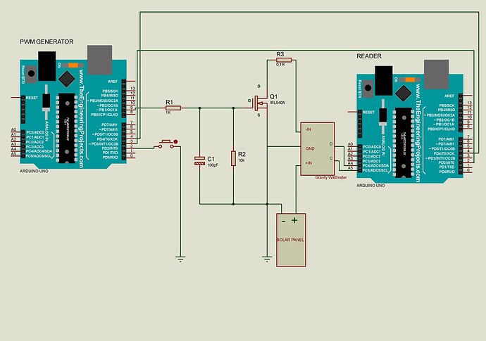
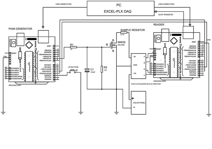
I have two Arduinos. The first Arduino provides a PWM signal to a MOSFET, incrementing the OCR1A register value step by step. I achieve this by continuously pressing a button connected to digital pin 2 within an if loop. The MOSFET adjusts the current level in a circuit accordingly. The second Arduino reads the current changes, voltage, and power using a wattmeter. I want to receive a reading on the second Arduino every time the first Arduino increments the OCR1A value. Only a button is connected to digital pin 2 on the first Arduino, and the digital pins 4 on both Arduinos are physically connected. What might be wrong with the code?
I don't understand how the interrupt function works completely. I received programming assistance from ChatGPT, but it keeps insisting that I can use pin 2, which is connected to a button, as an interrupt pin. This doesn't make sense to me. Pin 2 is internally built with a pull-up and constantly receives a low signal. How can I activate an interrupt triggered by a rising edge? I don't understand all of this. Please help.

#define Up 2                                             // Pin 2 teki artırma butonu                
int stateUp;                                             // Yukarı butonunun bilgisini tutacak değişken
const int stepPin = 4;                                   //değeri bir daha değiştirilemez türde integer bir değişken
volatile bool stepTriggered = false;                      //Kesme işlevlerinde kullanılan değişkenler "volatile" olarak işaretlenir, çünkü bu değişkenlerin değerleri donanım tarafından değiştirilebilir ve bu değişiklikler hemen işlenmelidir./


void setup() 
{
 
pinMode(Up, INPUT_PULLUP);                              // Up butonuna dahili pull-up uygulaması
pinMode(stepPin, OUTPUT);
digitalWrite(stepPin, LOW);
attachInterrupt(digitalPinToInterrupt(2), triggerStep, RISING);                             
 
  DDRB |= (1 << DDB1) | (1 << DDB2);                     // Set ports
  TCCR1A = (1 << COM1A1) | (1 << COM1B1) | (1 << WGM11); // Fast PWM mode    
  TCCR1B = (1 << WGM12) | (1 << WGM13) | (1 << CS10);    // Fast PWM mode, no clock prescaling possible
  OCR1A = 0;                                          // Start PWM just below MOSFET turn on
  ICR1 = 8191;                                           // Set the number of PWM steps
Serial.begin(115200);                                    // Start communication with serial monitor
}

void loop() 
{  stateUp=digitalRead(Up);
   if(stateUp==LOW){
  OCR1A++;
  delay(20); 
 Serial.println(OCR1A);}
 if (stepTriggered) 
 { 
    stepTriggered = false;
    digitalWrite(stepPin, HIGH);
    delay(1); 
    digitalWrite(stepPin, LOW);
  }
}
void triggerStep() {
  // Adım sinyali kesme işlevi
  stepTriggered = true;
}
#include <Wire.h>
#include "DFRobot_INA219.h"


DFRobot_INA219_IIC     ina219(&Wire, INA219_I2C_ADDRESS4);

// Revise the following two paramters according to actual reading of the INA219 and the multimeter
// for linearly calibration
float ina219Reading_mA = 1000;
float extMeterReading_mA = 1000;

void setup(void) 
{   
    Serial.begin(115200);
    while(!Serial);
    Serial.println();
    while(ina219.begin() != true) {
    Serial.println("INA219 begin faild");
    delay(2000);}

    //Linear calibration
    ina219.linearCalibrate(/*The measured current before calibration*/ina219Reading_mA, /*The current measured by other current testers*/extMeterReading_mA);

    Serial.println();
    Serial.println("CLEARSHEET");
    Serial.println("LABEL,Date,Time,Bus Voltage(V), Shunt Voltage(mV), Current(mA), Power(mW)");
}

void loop(void)

{if (digitalRead(4)==HIGH)
 {Serial.print("DATA,DATE,TIME,");
 Serial.print(ina219.getBusVoltage_V(), 2);
 Serial.print(",");
 Serial.print(ina219.getShuntVoltage_mV(), 3);
 Serial.print(",");
 Serial.print(ina219.getCurrent_mA(), 1);
 Serial.print(",") ;  
 Serial.print(ina219.getPower_mW(), 1);
 Serial.print(",");
 Serial.println(""); 
 delay(100);
}}
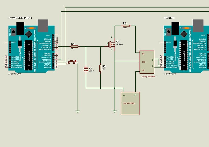
What Arduino boards?

Please post a schematic.

Both models are Arduino Uno. I don't have the ability to draw schematics, but I will add a hand-drawn understandable version shortly.

Please explain more about this. With the INPUT_PULLUP is should read high unless the button is pressed.

Your interrupt mode is Rising, so the interrupt will be when the button is released. OCR1A can be incremented many times before the button is released, but you will only get one interrupt.

Why have you chosen to use an interrupt on release to trigger the signal to the other arduino, rather than just sending the signal each time OCR1A is incremented? No interrupts required.

You are likely to have issues with button bounce.

DOC-20231020-WA0018..pdf (1.1 MB)
I'm not an expert in Arduino; I'm just trying to use it in my application. When I attempted to use pin control instead of interrupts, I couldn't get any readings, and I spent a long time trying to develop it. Especially since speed is required (OCR1A register should be able to scan between 0-9000 within 1-2 minutes), I asked ChatGPT for advice, and it recommended interrupts. It seems to be working in this way (I changed the interrupt pin to 3 and connected it to information coming from the reading Arduino). However, there are still some things that don't sit well with me. Your guidance would make me very happy. It's a thesis project, and everything is squeezed into a very short time frame. I'll try to add the schematic as soon as possible. I can only send the edits this way because I have to leave the computer. I hope it's understandable.

It's really best to post any code in the posting using the code tags like you did in your first post.

The schematic will be good as well.

However, there are still some things that don't sit well with me

Please explain in detail what issues you are having.

What does the code do that you don't want it to do?

What does the code not do that you want it to do?

.

Gotta be more to this. That's between 150 and 75/second. Trivially small. What else is slowing your code down so drastically?

Still waiting for...

Both models are Arduino Uno. I don't have the ability to draw schematics, but I will add a hand-drawn understandable version shortly.

I transfer the data to Excel and monitor it. When I remove the 20 ms delay, Excel crashes, so I can't increase the speed further. Maybe it's something I haven't been able to do. I still can't access my computer because I'm at work. When I get home, the first thing I'll do is prepare a diagram and send it to you.

I apologize, it took me quite a while to draw the schematic. Proteus wasn't installed on my computer, and it took hours. I also had to change some pins in the software. To be honest, it's challenging to determine if the software fully meets my requirements this way. The reason is this: I want the 1st Arduino to increase its PWM signal with each step, and when it does, the 2nd Arduino should perform a single read. After the 2nd Arduino finishes its read, the 1st one should advance to the next step. In other words, I want them to work sequentially, without skipping any data corresponding to each step, without any data loss. However, because the differences between steps are very small, I can't tell if data is being skipped or not during testing. This is actually my question: Will these two Arduinos work as I expect, without data loss, using this code?

THE PWM GENERATOR

#define Up 2                                             // Pin 2 teki artırma butonu                
int stateUp;                                             // Yukarı butonunun bilgisini tutacak değişken
const int stepPin = 4;                                   //değeri bir daha değiştirilemez türde integer bir değişken
volatile bool stepTriggered = false;                      //Kesme işlevlerinde kullanılan değişkenler "volatile" olarak işaretlenir, çünkü bu değişkenlerin değerleri donanım tarafından değiştirilebilir ve bu değişiklikler hemen işlenmelidir./
void setup() 
{
 
pinMode(Up, INPUT_PULLUP);                              // Up butonuna dahili pull-up uygulaması
pinMode(stepPin, OUTPUT);
digitalWrite(stepPin, LOW);
attachInterrupt(digitalPinToInterrupt(3), triggerStep, RISING);                             
 
  DDRB |= (1 << DDB1) | (1 << DDB2);                     // Set ports
  TCCR1A = (1 << COM1A1) | (1 << COM1B1) | (1 << WGM11); // Fast PWM mode    
  TCCR1B = (1 << WGM12) | (1 << WGM13) | (1 << CS10);    // Fast PWM mode, no clock prescaling possible
  OCR1A = 0;                                          // Start PWM just below MOSFET turn on
  ICR1 = 8191;                                           // Set the number of PWM steps
Serial.begin(115200);                                    // Start communication with serial monitor
}

void loop() 
{  stateUp=digitalRead(Up);
   if(stateUp==LOW){
  OCR1A++;
  delay(20); 
 Serial.println(OCR1A);}
 if (stepTriggered) 
 { 
    stepTriggered = false;
    digitalWrite(stepPin, HIGH);
    delay(1); 
    digitalWrite(stepPin, LOW);
  }
}
void triggerStep() {
  // Adım sinyali kesme işlevi
  stepTriggered = true;
}

THE WATTMETER

> #include <Wire.h>
> #include "DFRobot_INA219.h"
> 
> 
> DFRobot_INA219_IIC     ina219(&Wire, INA219_I2C_ADDRESS4);
> 
> // Revise the following two paramters according to actual reading of the INA219 and the multimeter
> // for linearly calibration
> float ina219Reading_mA = 1000;
> float extMeterReading_mA = 1000;
> const int ReadPin = 2;
> void setup(void) 
> {   pinMode(4, INPUT);
>     Serial.begin(115200);
>     while(!Serial);
>     Serial.println();
>     while(ina219.begin() != true) {
>     Serial.println("INA219 begin faild");
>     delay(2000);}
> 
>     //Linear calibration
>     ina219.linearCalibrate(/*The measured current before calibration*/ina219Reading_mA, /*The current measured by other current testers*/extMeterReading_mA);
> 
>     Serial.println();
>     Serial.println("CLEARSHEET");
>     Serial.println("LABEL,Date,Time,Bus Voltage(V), Shunt Voltage(mV), Current(mA), Power(mW)");
> }
> 
> void loop(void)
> 
> {if (digitalRead(4)==HIGH)
>   digitalWrite(ReadPin,LOW);
>  {Serial.print("DATA,DATE,TIME,");
>  Serial.print(ina219.getBusVoltage_V(), 2);
>  Serial.print(",");
>  Serial.print(ina219.getShuntVoltage_mV(), 3);
>  Serial.print(",");
>  Serial.print(ina219.getCurrent_mA(), 1);
>  Serial.print(",") ;  
>  Serial.print(ina219.getPower_mW(), 1);
>  Serial.print(",");
>  Serial.println(""); 
>  delay(100);
>  digitalWrite (ReadPin,HIGH);
> }}

They're both uno. I could draw the schematic finally. Additionally if you could read my last answer I made some changes and clearfied my question.
Thank yo so much.

I understand what you want, and I will set up to do some testing. It's not clear to me if you have the handshake worked out correctly in your code.

It's not clear to me that the 1 ms pulse sent out by the pwm generator on the step pin (4) is long enough for the reading on the wattmeter with all the serial printing and delays.

You may want to use an interrupt on both unos.

I thought the same thing. Theoretically, it doesn't seem like it won't work, but in practice, it's very difficult to see what will happen with such a short-term physical change. I don't know exactly how long it takes for a physical change to be perceived, and I also don't know how to control it. I tried with a measuring tool (a voltmeter), of course, but it didn't detect anything:) For example, when I tried to make sequential operations with only 'if' statements in the first Arduino without using interrupts, the second Arduino never entered the loop (so it seems like there wasn't enough time for it to query and enter the reading loop, I guess). I tried it with an interrupt, and it worked then.

I really appreciate your interest. I'm grateful for your kindness and help.

This may be irrelevant, but please give it a try. Connect the grounds of the two Unos. Right now, your signals are relying on a ground reference via the two USB cables to the computer(s?) powering them.
For your schematic, that's a nice start. However, you should always include complete information about the power source(s), and clarify whether there is one computer or more involved in the setup(when there is more than one Arduino). This is because power sourcing is one of the most common problem areas for beginners(and sometimes, not-so-beginners). If you had included that info, I would have more confidence in telling you whether you have a ground reference problem; as it is, I can only speculate.

They are powered from the same computer, but when I previously encountered issues with the operation of the MOSFET, I considered that it might be due to the reason you mentioned (I thought that not all grounds in the circuit were connected, causing a potential difference that could affect the operation of the MOSFET), so I connected all the grounds. Do you think I should do that?

Should I connect the grounds of Arduino and all other components?

As you can see, in the circuit, the component serving as the power source for the MOSFET is the solar panel. As I mentioned, when I do this, two Arduinos powered by the same computer, the negative terminal of the solar panel, the source terminal of the MOSFET are all being connected. Is this a correct application?

So you're saying the drawing in post#11 is incomplete? There is a connection from each Arduino GND to the GND of the "gravity wattmeter"? Could we have a link to some documentation for that device?

Unfortunately, I worked until midnight and, after coming home, I installed the program and spent long hours on the drawing. Since I'm not very experienced, there are some shortcomings. I hope this last one is useful. Below, you can see the information for the Arduino-compatible wattmeter.

My main problem is not being able to determine whether the software is working as expected. I can't figure out if my software ensures that two Arduinos run in sequence, the data flow looks healthy, but it has been tested on a linear power source, and when connected to a solar panel (if the code does not serve the purpose of sequential operation), it causes significant data jumps.

#define Up 2                                             // Pin 2 teki artırma butonu                
int stateUp;                                             // Yukarı butonunun bilgisini tutacak değişken
const int stepPin = 4;                                   //değeri bir daha değiştirilemez türde integer bir değişken
volatile bool stepTriggered = false;                      //Kesme işlevlerinde kullanılan değişkenler "volatile" olarak işaretlenir, çünkü bu değişkenlerin değerleri donanım tarafından değiştirilebilir ve bu değişiklikler hemen işlenmelidir./
void setup() 
{
 
pinMode(Up, INPUT_PULLUP);                              // Up butonuna dahili pull-up uygulaması
pinMode(stepPin, OUTPUT);
digitalWrite(stepPin, LOW);
attachInterrupt(digitalPinToInterrupt(3), triggerStep, RISING);                             
 
  DDRB |= (1 << DDB1) | (1 << DDB2);                     // Set ports
  TCCR1A = (1 << COM1A1) | (1 << COM1B1) | (1 << WGM11); // Fast PWM mode    
  TCCR1B = (1 << WGM12) | (1 << WGM13) | (1 << CS10);    // Fast PWM mode, no clock prescaling possible
  OCR1A = 0;                                          // Start PWM just below MOSFET turn on
  ICR1 = 8191;                                           // Set the number of PWM steps
Serial.begin(115200);                                    // Start communication with serial monitor
}

void loop() 
{  stateUp=digitalRead(Up);
   if(stateUp==LOW){
  OCR1A++;
  delay(20); 
 Serial.println(OCR1A);}
 if (stepTriggered) 
 { 
    stepTriggered = false;
    digitalWrite(stepPin, HIGH);
    delay(1); 
    digitalWrite(stepPin, LOW);
  }
}
void triggerStep() {
  // Adım sinyali kesme işlevi
  stepTriggered = true;
}
#include <Wire.h>
#include "DFRobot_INA219.h"


DFRobot_INA219_IIC     ina219(&Wire, INA219_I2C_ADDRESS4);

// Revise the following two paramters according to actual reading of the INA219 and the multimeter
// for linearly calibration
float ina219Reading_mA = 1000;
float extMeterReading_mA = 1000;
const int ReadPin = 2;
void setup(void) 
{   pinMode(4, INPUT);
    Serial.begin(115200);
    while(!Serial);
    Serial.println();
    while(ina219.begin() != true) {
    Serial.println("INA219 begin faild");
    delay(2000);}

    //Linear calibration
    ina219.linearCalibrate(/*The measured current before calibration*/ina219Reading_mA, /*The current measured by other current testers*/extMeterReading_mA);

    Serial.println();
    Serial.println("CLEARSHEET");
    Serial.println("LABEL,Date,Time,Bus Voltage(V), Shunt Voltage(mV), Current(mA), Power(mW)");
}

void loop(void)

{if (digitalRead(4)==HIGH)
  {digitalWrite(ReadPin,LOW);
 Serial.print("DATA,DATE,TIME,");
 Serial.print(ina219.getBusVoltage_V(), 2);
 Serial.print(",");
 Serial.print(ina219.getShuntVoltage_mV(), 3);
 Serial.print(",");
 Serial.print(ina219.getCurrent_mA(), 1);
 Serial.print(",") ;  
 Serial.print(ina219.getPower_mW(), 1);
 Serial.print(",");
 Serial.println(""); 
 delay(100);
 digitalWrite (ReadPin,HIGH);
}}

II have attached the modified schematic in another message, but you may not have received a notification because I didn't respond to you. In the initial software, the condition for the interrupt is for pin 3 to be HIGH. This pin is hardware-wise connected to pin 2 on Arduino 2, and that pin is inside a loop with a condition that requires interrupt 1 on Arduino 1 to occur and set pin 4 to HIGH. This setup makes it seem like Arduino 2 shouldn't be reading at all. However, it is still reading. I'm not sure if it's functioning correctly. How should I rearrange the pins or conditions for them to perform sequential tasks? I need help with this

See if these sketches give you a better hand shake using interrupts on both sides.

PWM generator code

I have added debounce to the button on pin 2 by reading it on a 50 ms timer. Connect stepPin 4 to pin 3 of the Reader where it will be sensed with an interrupt. The pwm generator will get a response from the reader with an interrupt on pin3 when the step signal is received.

#define Up 2  // Pin 2 teki artırma butonu
int stateUp;
int lastStateUp;                      // Yukarı butonunun bilgisini tutacak değişken
const int stepPin = 4;                //değeri bir daha değiştirilemez türde integer bir değişken
volatile bool stepTriggered = false;  //Kesme işlevlerinde kullanılan değişkenler "volatile" olarak işaretlenir, çünkü bu değişkenlerin değerleri donanım tarafından değiştirilebilir ve bu değişiklikler hemen işlenmelidir./
volatile bool response = true; //enable first sending

void setup()
{
  pinMode(Up, INPUT_PULLUP);  // Up butonuna dahili pull-up uygulaması
  pinMode(stepPin, OUTPUT);
  digitalWrite(stepPin, LOW);
  noInterrupts();
  attachInterrupt(digitalPinToInterrupt(3), getResponse, RISING); //response interrupt from ina reader
  interrupts();
  DDRB |= (1 << DDB1) | (1 << DDB2);                      // Set ports
  TCCR1A = (1 << COM1A1) | (1 << COM1B1) | (1 << WGM11);  // Fast PWM mode
  TCCR1B = (1 << WGM12) | (1 << WGM13) | (1 << CS10);     // Fast PWM mode, no clock prescaling possible
  OCR1A = 0;                                              // Start PWM just below MOSFET turn on
  ICR1 = 8191;                                            // Set the number of PWM steps
  Serial.begin(115200);
  delay(200);  // Start communication with serial monitor
  Serial.println("Start sending signal on button press");
}

void loop()
{
  //debounce button by reading every 50 ms 
  static unsigned long  lastRead = 0;
  unsigned long now = millis(); 
  if(now- lastRead >= 50)
  {
  stateUp = digitalRead(Up);
  lastRead = now;
  }
  
  if (stateUp == LOW)
  {
    if(response) //only send to ina reader if response back from reader to last send
    {
    OCR1A++;
    Serial.println(OCR1A);
    stepTriggered = true; //send next step after response
    response = false;
    }
  }
   lastStateUp = stateUp;
   
  if (stepTriggered) //pin4 pulse triggers interrupt in ina reader
  {
    stepTriggered = false;
    digitalWrite(stepPin, HIGH);
    delay(1);
    digitalWrite(stepPin, LOW);
  }
}
void getResponse() 
{
  response = true;
}

Reader Program reads with an interrupt and responds that it was received.

#include <Wire.h>
#include "DFRobot_INA219.h"
DFRobot_INA219_IIC ina219(&Wire, INA219_I2C_ADDRESS4);

// Revise the following two parameters according to actual reading of the INA219 and the multimeter
// for linearly calibration
float ina219Reading_mA = 1000;
float extMeterReading_mA = 1000;
const int readPin = 2;  //connect to pin 3 on other Arduino
volatile boolean signalReceived = false;

void setup(void)
{
  pinMode(readPin, OUTPUT);  // send signal to other Arduino
  pinMode(3, INPUT_PULLUP);  //receive signal from other Arduino
  Serial.begin(115200);
  Serial.println("Starting");
  while (ina219.begin() != true)
  {
    Serial.println("INA219 begin faild");
    delay(2000);
    noInterrupts();
    attachInterrupt(digitalPinToInterrupt(3), signalFromArduino, FALLING);
    interrupts();
    //Linear calibration
    ina219.linearCalibrate(/*The measured current before calibration*/ ina219Reading_mA, /*The current measured by other current testers*/ extMeterReading_mA);
    Serial.println();
    Serial.println("CLEARSHEET");
    Serial.println("LABEL,Date,Time,Bus Voltage(V), Shunt Voltage(mV), Current(mA), Power(mW)");
  }

  void loop(void)
  {
    if (signalReceived)
    {
      signalReceived = false;
      digitalWrite(readPin, LOW);  // signal back to other Arduino
      Serial.println("DATA,DATE,TIME,");
      Serial.print(ina219.getBusVoltage_V(), 2);
      Serial.print(",");
      Serial.print(ina219.getShuntVoltage_mV(), 3);
      Serial.print(",");
      Serial.print(ina219.getCurrent_mA(), 1);
      Serial.print(",");
      Serial.print(ina219.getPower_mW(), 1);
      Serial.print(",");
      Serial.println("");
      delay(100);
      digitalWrite(readPin, HIGH);
      Serial.println();
    }
  }

  void signalFromArduino()
  {
    signalReceived = true;
  }

Thank you very much for your effort. I really want to try it out on solar panel. I should wait for my day off (Friday) for that. I couldn't respond immediately, so please forgive me. Thanks again. I'll try it and get back to you.

cattledog via Arduino Forum <notifications@arduino.discoursemail.com>, 24 Eki 2023 Sal, 09:37 tarihinde şunu yazdı:

This topic was automatically closed 180 days after the last reply. New replies are no longer allowed.