0V power connects to pin 5 of the RS232 connector AND to the negative (-ve) of the 15V supply
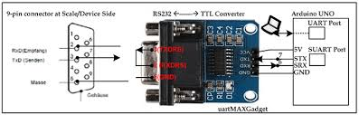
To the Arduino GND just like in the diagram you show
+15v to which pin of rs232 converter db9 pin
negative of 15v to pin5 but +15v to which pin
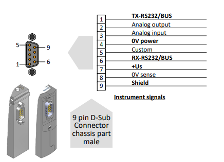
Pin 4 of your mass flow device connects to -15V AND pin 5 of the RS232 DB9 converter module
Pin 7 of the mass flow device connects to the +15V
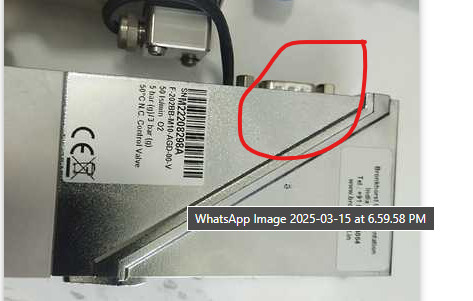
in hook up diagram the marked area is the end on mass flow controller correct?

these both end are same correct?
And in the hook up diagram in the male pin side why did they interconnect 8 and 9 what does it mean
Because in the diagram it is mentioned that the other marked end in cabel connector end .
so if i am not wrong pin 5 mfc is -15v pin7 of mfc is +15v
in hook up diagram the marked area is the end on mass flow controller correct?
No.
It's part of some T adaptor for the MFC
I downloaded this document from the Bronkhost website.
It shows the connections.
916118-Hook-up-diagram-laboratory-style-Optional-bus-and-IO-configurations1.pdf (719.1 KB)
You should read the operators manual for your MFC to learn how to use it
From the manual:
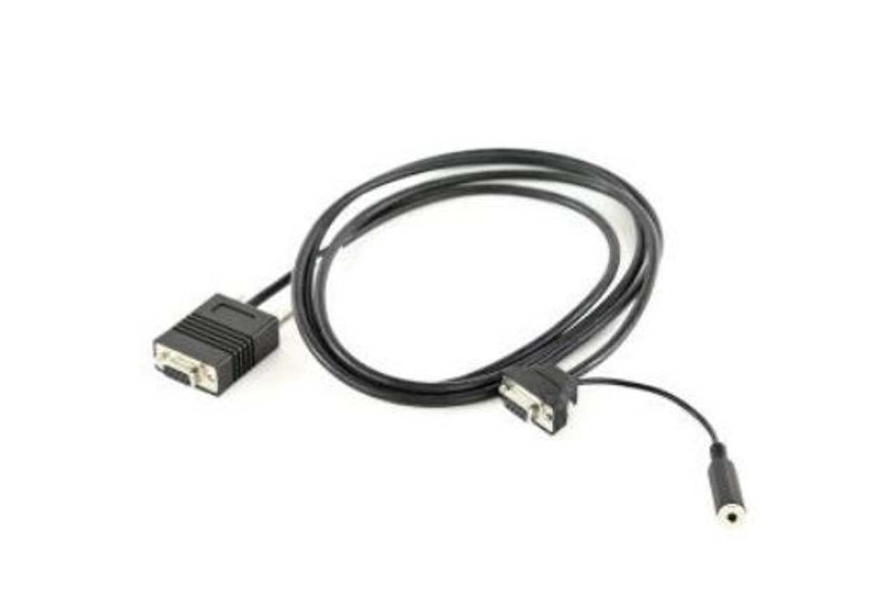
"A special RS232 cable (7.03.366) can be ordered separately. It consists of a T-part with 1 male and 1 female sub-D 9 connector on one instrument-side and a normal female sub-D 9 connector on the side of the computer. By means of this cable it is possible to offer RS232 communication and still be able to connect power-supply and analog interface through the (analog) sub-D 9 connector."
That is what you show in post #27
Once you have the hardware connected correctly, then you can work on the software.
i have changed the connection as per the diagram and used this connector
and ensured that the connections are same as the pin mentions in the below diagram
Now i have uploaded my code and runned it , but i didnt get any response message
This is the module i am using to communcate between arduino and mfc

Pins 8 and 9 on a standard 9 pin RS232 connector are Request To Send (RTS) and Clear To Send (CTS).
These are handshaking signals that are required by some systems to communicate correctly.
You don't use hardware handshaking, and so the connection is un-necessary.
Bronkhorst have included them so that their valve will work with any hardware.
Are the connections as I show in post #19 ?
See post #19 for proper connections
I did proper connections and uploaded my code , now what to do
Connect the RS232 board to Mega as follows
Mega   RS232 board
RX1  <-- Rx
TX1  --> Tx
GND  --  GND
5V   --  Vcc
Connect the MFC to the RS232 board as shown in post #19
Connect 15V power to MFC as shown in post #19
Then we can work on the software.
I am ready
Post your code