Interfacing Arduino with 74HC595 and a 7-Seg

Some of you may recognize me from the thread about interfacing an HD44780 display and DS18S20 temperature sensors. It was a great learning experience! Thanks to everyone that helped me get it working :slight_smile:

For my next project, Ive picked up some CC 7-seg displays and some 74HC595 shift registers. Id like to do the same thing (read the temperature) and display it to the 7-seg's (I started with the LCD because saying lcd.write(temp); was easier than learning how to shift data ;)).

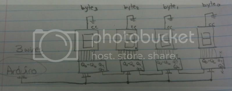
Ive connected ST_CP to pin 8, SH_CP to pin 12, and DS to pin 11. I have Q0 connected to the 'a' segment (I dont know if I labelled properly, but I started with 'a' being the top segment, and 'b' being the top-right segment, and continuing on in a clockwise rotation) all the way up to 'g' connected to Q7.

Im using the following code from the shiftOut tutorial, modified a bit (explained later):

//**************************************************************//
//  Name    : shiftOutCode, Predefined Array Style              //
//  Author  : Carlyn Maw, Tom Igoe                           //
//  Date    : 25 Oct, 2006                                      //
//  Version : 1.0                                               //
//  Notes   : Code for using a 74HC595 Shift Register           //
//          : to count from 0 to 255                            //
//****************************************************************

//Pin connected to ST_CP of 74HC595
int latchPin = 8;
//Pin connected to SH_CP of 74HC595
int clockPin = 12;
////Pin connected to DS of 74HC595
int dataPin = 11;

//holders for infromation you're going to pass to shifting function
byte data;
byte dataArray[8];

void setup() {
  //set pins to output because they are addressed in the main loop
  pinMode(latchPin, OUTPUT);
  Serial.begin(9600);

  //Arduino doesn't seem to have a way to write binary straight into the code 
  //so these values are in HEX.  Decimal would have been fine, too. 
  dataArray[0] = 0x00; // off
  dataArray[1] = 0x01; // a
  dataArray[2] = 0x02; // b
  dataArray[3] = 0x04; // c
  dataArray[4] = 0x08; // d
  dataArray[5] = 0x10; // e
  dataArray[6] = 0x20; // f
  dataArray[7] = 0x40; // g
 
  //function that blinks all the LEDs
  //gets passed the number of blinks and the pause time
  blinkAll(2,500); 
}

void loop() {


  for (int j = 0; j < 10; j++) {
    //load the light sequence you want from array
    data = dataArray[j];
    //ground latchPin and hold low for as long as you are transmitting
    digitalWrite(latchPin, 0);
    //move 'em out
    shiftOut(dataPin, clockPin, data);   
    //return the latch pin high to signal chip that it 
    //no longer needs to listen for information
    digitalWrite(latchPin, 1);
    delay(1000);
  }
}


// the heart of the program
void shiftOut(int myDataPin, int myClockPin, byte myDataOut) {
  // This shifts 8 bits out MSB first, 
  //on the rising edge of the clock,
  //clock idles low

  //internal function setup
  int i=0;
  int pinState;
  pinMode(myClockPin, OUTPUT);
  pinMode(myDataPin, OUTPUT);

  //clear everything out just in case to
  //prepare shift register for bit shifting
  digitalWrite(myDataPin, 0);
  digitalWrite(myClockPin, 0);

  //for each bit in the byte myDataOut[ch65533]
  //NOTICE THAT WE ARE COUNTING DOWN in our for loop
  //This means that %00000001 or "1" will go through such
  //that it will be pin Q0 that lights. 
  for (i=7; i>=0; i--)  {
    digitalWrite(myClockPin, 0);

    //if the value passed to myDataOut and a bitmask result 
    // true then... so if we are at i=6 and our value is
    // %11010100 it would the code compares it to %01000000 
    // and proceeds to set pinState to 1.
    if ( myDataOut & (1<<i) ) {
      pinState= 1;
    }
    else {      
      pinState= 0;
    }

    //Sets the pin to HIGH or LOW depending on pinState
    digitalWrite(myDataPin, pinState);
    //register shifts bits on upstroke of clock pin  
    digitalWrite(myClockPin, 1);
    //zero the data pin after shift to prevent bleed through
    digitalWrite(myDataPin, 0);
  }

  //stop shifting
  digitalWrite(myClockPin, 0);
}


//blinks the whole register based on the number of times you want to 
//blink "n" and the pause between them "d"
//starts with a moment of darkness to make sure the first blink
//has its full visual effect.
void blinkAll(int n, int d) {
  digitalWrite(latchPin, 0);
  shiftOut(dataPin, clockPin, 0);
  digitalWrite(latchPin, 1);
  delay(200);
  for (int x = 0; x < n; x++) {
    digitalWrite(latchPin, 0);
    shiftOut(dataPin, clockPin, 255);
    digitalWrite(latchPin, 1);
    delay(d);
    digitalWrite(latchPin, 0);
    shiftOut(dataPin, clockPin, 0);
    digitalWrite(latchPin, 1);
    delay(d);
  }
}

Ive modified the array at the start to contain the different segments, and how I have them hooked up:

Qx - seg -- bin -- dec - hex
Q0 - a - 00000001 - 01 - 01
Q1 - b - 00000010 - 02 - 02
Q2 - c - 00000100 - 04 - 04
Q3 - d - 00001000 - 08 - 08
Q4 - e - 00010000 - 16 - 10
Q5 - f - 00100000 - 32 - 20
Q6 - g - 01000000 - 64 - 40
Q7 - open -----------------

And so far, its working great! However, I plan on having four 7-seg displays per sensor (one per number, and two more at the end hard-wired to "°C"). Does this mean I will need four shift registers per sensor? I picked up four just in case (and if I dont need them Im sure I will use them in the future). What is the best way for me to connect all four displays? Other than the chip count, shift registers seem like a good way as I only need three wires per group of display. Im not looking for blocks of code at this point (however, if you have any I would definately appreciate them!); Im looking for ideas and suggestions. Please keep in mind that I do have a small programming background, but Im more of a hardware guy (Im in Uni for Electrical Engineering Tech), so you will most likely need to be basic with me for a little longer when it comes to code, until I catch on :wink: Thanks!

Hey again! It looks like you are still having a good time!

You can get away with just one shift register if you want to multiplex the display. If you switch the common cathodes to ground for, say, 1/60 of a second in a round robin fashion, shifting the new character in before you switch, your eye will think the display is constant.

The way you calculate the value of the anode resistors is to assume 4 times the required current since at 25% duty cycle the average current will be Imax/4.

That should give you plenty to think about for a while. :slight_smile:

Thanks for the reply. After school, Ill start working on having it flash the displays, one by one. However, if I have four segments per sensor, and one shift register, that means Im going to need (4+3=) 7 wires per set of four displays. And since Id like to have two, that puts me up to 14 wires, which doesnt leave much room for anything else. Any ways of further reducing the amount of pins Ill need to use?

Use a demultiplex chip like the 74LS42, this will give you 8 output wires for only 3 address lines. Use these to switch the power on the anodes while pulling down the cathodes with the shift register.
An example of using the 74LS42 is to be found at:- Econo Monome

That looks backwards to me, Mike. Are you sure about that?

I was thinking the same thing. I chose common-cathode displays so I could turn them on with a 1. What you describe sounds like i would need to enable the displays with something like 1110 instead of 0001 which would make things more difficult for me.

That looks backwards to me,

Not sure what you are referring to but the schematic works so it must be right. :wink:

enable the displays with something like 1110 instead of 0001

Yes that is more convenient because you need to use that signal to switch the power with a PNP transistor or P-channel FET. These require logic 1 to turn them off so they are suited to the output of the 74LS42.

Not sure what you are referring to but the schematic works so it must be right.

Science can't explain it but it happens! :wink:

Yes, your LED matrix works fine, I'm sure, but OP has common cathode LED 7-segment displays. He is interested in driving the individual anode segments from the active high outputs of his 74HC595 shift register. Your suggestion would work if he used the 7442 to drive the common cathode connection for each digit, since the 7442 has active low outputs. Driving the anode segments with the 7442, on the other hand would take some pretty fast segment multiplexing or else would be pretty boring with only one segment lit per digit. You could use base 7 for your output. Two digits would be plenty for Celsius. :smiley:

Leaving that for Mike to sort out for the moment, you could use a 4511 BCD to 7-segment decoder + the 7442 and service up to 8 digits with 7 digital out pins.

Good, there's been some discussion while I was gone :slight_smile: While I was in class I drew up some stuff. Here goes:

Table showing segment/Qx association/bin/hex conversion:

Table showing hex value for the numbers 0-9 (tested and working! :))

Idea 1: Connecting the displays with only shift registers (for a total of 3 wires per group of displays):

Idea 2: Connecting the displays with a shift register and either a 2-to-4 line decoder (for multiplexing the displays) which would need five wires, or using a transistor (missing resistors - just a block diagram) for each display, for a total of seven wires per group of displays:

Now, some of these ideas may not even work, I was just trying to come up with ideas, to prove that Im serious about doing this (and not just trying to con you guys into doing my work for me!). So far, Idea 1 with one shift register per display seems the best, as the coding would be the easiest - I expect it would go something like this:

temp * 100 // remove the decimal (decimal hardwired on second display)
for each number in temp, starting with the 1's value
look up hex in table // if we need a 0, shift out 0x3F, etc
shift out

may be completely off, but hey, Im trying!

Those are all good ideas. Did you say the two displays on the right were displaying constant degree symbol and the "C"? In that case you could hard wire the characters although you'd have to fiddle with resistance to get the same brightness as your live digits. Probably a little too much "refining" as you might want to use those digits in the future.

Think about the code for the case where you have only one shift register. What do you have to do to maintain a reading in your live displays before the next refresh?

Think about the case where you have a shift register for each live digit. Ask yourself the same question.

What about if you have a chip that turns decodes BCD into 7 segment (4511)? Does that give you more or less time for other processing than the other two cases? Which strategy of multiplexing gives you least time to do other things? Which one affects the quality of the display the most or least if you stop doing it for a moment?

This is starting to sound too much like a homework assignment and it's supposed to be fun! :smiley:

Those are all good ideas. Did you say the two displays on the right were displaying constant degree symbol and the "C"? In that case you could hard wire the characters although you'd have to fiddle with resistance to get the same brightness as your live digits. Probably a little too much "refining" as you might want to use those digits in the future.

Yes, there will be two more displays to the right of these four, which will display "°C". I was planning on using a 1k pot and adjusting the brightness to match the others.

Think about the code for the case where you have only one shift register. What do you have to do to maintain a reading in your live displays before the next refresh?

To be honest, I havent even put any thought into this method, other than just 'can it be done'. Being as new as I am to writing code for a uC, Im planning on staying away from multiplexing for now, as that adds another element of unknown to my code, and I already dont know what Im doing as it is :wink:

Think about the case where you have a shift register for each live digit. Ask yourself the same question.

Unless Im misunderstanding you, wouldnt I just have to not start shifting until I poll the sensor? The shift register is going to keep the digit lit to whatever I have loaded into the latch until I load something else, right?

What about if you have a chip that turns decodes BCD into 7 segment (4511)? Does that give you more or less time for other processing than the other two cases? Which strategy of multiplexing gives you least time to do other things? Which one affects the quality of the display the most or least if you stop doing it for a moment?

Here, let me delve deep into my knowledge of multiplexing... The first kind :slight_smile: I know the idea behind it (switching displays on and off quickly to trick the mind into thinking theyre on all time), but Ive never seen it implemented in code or looked at the various methods.

This is starting to sound too much like a homework assignment and it's supposed to be fun! :smiley:

Ive never had a homework assignment like this! :stuck_out_tongue: Mine consisted of "create a circuit that uses a one-shot multivibrator to turn a 50kHz 80% duty cycle square wave into a 50kHz 50% duty cycle square wave." This sounds more like a big term project :wink:

As far as the decoder goes, you have to write the BCD code into the decoder for each displayed digit and then write the cathode for that digit low for your multiplex time. The digital out pins provide the latch function during the "on" time.

I think you will agree that out of the methods you've considered, the one with a shift register for each digit has the lowest overhead in terms of % of available processing time.

Another method would be use one shift register driving two BCD to 7 segment decoders where the shift register contains the two BCD digits instead of segment data. Just a different way, I don't suggest that it is better or worse.

Wow, you've got it easy. :slight_smile:

I was thinking the same thing. I chose common-cathode displays so I could turn them on with a 1. What you describe sounds like i would need to enable the displays with something like 1110 instead of 0001 which would make things more difficult for me.

Why would it make life more difficult?

Turning 0001 into 1110 is easy, you just use a logical NOT symbol, i.e. a ~ before your variable and it inverts it.

Ahh cool, like I said, I dont consider myself anything of a program, I didnt know ~ would invert it :stuck_out_tongue: Still, its just one fewer thing that Id have to do.

Mike's example was using FET inverters as anode drivers which required an active low to enable. OP already has common cathode displays and he is driving the anodes directly from the HC595. Agreed that he could just as easily drive those same anodes with FETs and negative logic from those same shift registers. He would not use 7442s to do that, however.

Maybe the difficulty would come from having to wire up all those extra transistors.

Im sure Id forget to invert the output in my first few tries, so that would likely screw me up too haha.

So far so good:

Looks plenty bright. What is your segment current? Are you multiplexing the one digit?

They are running at 5v and have a 510[ch937] resistor per segment, so each segment is getting (5v / 510[ch937] =) 9.8mA.

Ive just got the CC grounded and Im using the following code:

#include <Debounce.h>
#include <Button.h>

//**************************************************************//
//  Name    : shiftOutCode, Predefined Array Style              //
//  Author  : Carlyn Maw, Tom Igoe                           //
//  Date    : 25 Oct, 2006                                      //
//  Version : 1.0                                               //
//  Notes   : Code for using a 74HC595 Shift Register           //
//          : to count from 0 to 255                            //
//****************************************************************

//Pin connected to ST_CP of 74HC595
int latchPin = 8;
//Pin connected to SH_CP of 74HC595
int clockPin = 12;
////Pin connected to DS of 74HC595
int dataPin = 11;
int j = 1;

//holders for infromation you're going to pass to shifting function
byte data;
byte dataArray[10];
Button button = Button(10,PULLUP);

void setup() {
  //set pins to output because they are addressed in the main loop
  pinMode(latchPin, OUTPUT);
  Serial.begin(9600);

  //Arduino doesn't seem to have a way to write binary straight into the code 
  //so these values are in HEX.  Decimal would have been fine, too. 
  dataArray[0] = 0x3F; // 0
  dataArray[1] = 0x06; // 1
  dataArray[2] = 0x5B; // 2
  dataArray[3] = 0x4F; // 3
  dataArray[4] = 0x66; // 4
  dataArray[5] = 0x6D; // 5
  dataArray[6] = 0x7C; // 6
  dataArray[7] = 0x07; // 7
  dataArray[8] = 0x7F; // 8
  dataArray[9] = 0x67; // 9

  data = dataArray[0];
  //ground latchPin and hold low for as long as you are transmitting
  digitalWrite(latchPin, 0);
  //move 'em out
  shiftOut(dataPin, clockPin, data);   
  //return the latch pin high to signal chip that it 
  //no longer needs to listen for information
  digitalWrite(latchPin, 1);
}

void loop() 
{
  if (button.uniquePress())
  {
    if (j < 10)
    {
      data = dataArray[j];
      //ground latchPin and hold low for as long as you are transmitting
      digitalWrite(latchPin, 0);
      //move 'em out
      shiftOut(dataPin, clockPin, data);   
      //return the latch pin high to signal chip that it 
      //no longer needs to listen for information
      digitalWrite(latchPin, 1);
      j++;
    }
    else if (j == 10)
    {
      j = 0;
      data = dataArray[j];
      //ground latchPin and hold low for as long as you are transmitting
      digitalWrite(latchPin, 0);
      //move 'em out
      shiftOut(dataPin, clockPin, data);   
      //return the latch pin high to signal chip that it 
      //no longer needs to listen for information
      digitalWrite(latchPin, 1);
    } 
    delay(200);
  }

  /*
  for (int j = 0; j < 10; j++) {
   //load the light sequence you want from array
   data = dataArray[j];
   //ground latchPin and hold low for as long as you are transmitting
   digitalWrite(latchPin, 0);
   //move 'em out
   shiftOut(dataPin, clockPin, data);   
   //return the latch pin high to signal chip that it 
   //no longer needs to listen for information
   digitalWrite(latchPin, 1);
   delay(1000);
   }
   }
   */
}

// the heart of the program
void shiftOut(int myDataPin, int myClockPin, byte myDataOut) 
{
  // This shifts 8 bits out MSB first, 
  //on the rising edge of the clock,
  //clock idles low

  //internal function setup
  int i=0;
  int pinState;
  pinMode(myClockPin, OUTPUT);
  pinMode(myDataPin, OUTPUT);

  //clear everything out just in case to
  //prepare shift register for bit shifting
  digitalWrite(myDataPin, 0);
  digitalWrite(myClockPin, 0);

  //for each bit in the byte myDataOut?
  //NOTICE THAT WE ARE COUNTING DOWN in our for loop
  //This means that %00000001 or "1" will go through such
  //that it will be pin Q0 that lights. 
  for (i=7; i>=0; i--)  {
    digitalWrite(myClockPin, 0);

    //if the value passed to myDataOut and a bitmask result 
    // true then... so if we are at i=6 and our value is
    // %11010100 it would the code compares it to %01000000 
    // and proceeds to set pinState to 1.
    if ( myDataOut & (1<<i) ) {
      pinState= 1;
    }
    else {      
      pinState= 0;
    }

    //Sets the pin to HIGH or LOW depending on pinState
    digitalWrite(myDataPin, pinState);
    //register shifts bits on upstroke of clock pin  
    digitalWrite(myClockPin, 1);
    //zero the data pin after shift to prevent bleed through
    digitalWrite(myDataPin, 0);
  }

  //stop shifting
  digitalWrite(myClockPin, 0);

}

Im working on getting the other three segments hooked up :slight_smile:

Yay!

You can make binary constants. They are limited to type byte.

dataArray[0] = B111111; // 0

How do I string hex/binary together? Like if I want the two displays to display 62, Id have to shift out 0x7C5B (shifting 5B first, then 7C). In binary itd be 01111100 sent first, then 01011011, to fill the register like this:

 01011011 | 01111100
+---------+---------+
     6            2

EDIT Would I need to join them together? Now that I think about it, I should just be able to shift out the LSByte, then the MSByte, right?