Hello!
I created this account so that I could ask you guys something. I normally can figure things out by scouring these forums for hours, but I can't seem to figure this one out.
What I am trying to do is have an Arduino Nano use SPI to interface with a AD9837, which in turn will have its own output circulate back to A0 on the arduino. So basically
Arduino SPI -> Waveform IC -> Arduino ADC
The point of this is to show some people the effect that body capacitance has on different frequencies.
So far I have been able to hack together a sketch that successfully writes the bits to the IC and I have hooked it up to my stereo to confirm that it works. Great. It does. So I figured I could just connect the output of that to the ADC on the arduino. Is there something that I am missing here?
I attached my .ino file that I am using, as well as a picture of the current setup.
#include <SPI.h>

#define AD9833_F_MCLK 1000000          // 1MHz clock
#define AD9833_2POW28 268435456         // 2 to the power of 28
#define FSYNC SS //Pin 10 on NANO

#define F 120

float Freturn[F], freqVal[F];
//byte sizeOfFArray = F * 3;


void setup() {
  Serial.begin(115200);
  SPI.setDataMode(SPI_MODE2);
  SPI.begin();

  pinMode(FSYNC, OUTPUT);
  digitalWrite(FSYNC, LOW); //High means no transmission to AD9837
  AD9833_Freq(0);//Set frequency of AD9837 OUT
  AD9833_Phase(0);//Set Phase of AD9837 OUT
  //delay(20);
  AD9833_Control(0x0000);//Not sure what this one does yet
  digitalWrite(FSYNC, HIGH);

  for (int i = 0; i < F; i++) {//Set all return values to 0 to start
    Freturn[i] = 0;
  }
}

void loop() {


  for(byte d=0;d<F;d++){
    int a=analogRead(0);
    delayMicroseconds(2);//Give a little buffer before stopping signal
    stopGenerator();
    AD9833_Freq(d);
    AD9833_Phase(0);//Set Phase of AD9837 OUT
    AD9833_Control(0x0000);//Not sure what thi,s one does yet

    Freturn[d]=Freturn[d]*0.5+(float)(a)*0.5; //Filter results
    Serial.println(Freturn[28]);
    freqVal[d]=d;
  }


}

void stopGenerator(){
  AD9833_Freq(0);
  AD9833_Phase(0);//Set Phase of AD9837 OUT
  AD9833_Control(0x0000);//Not sure what this one does yet
}


void AD9833_Control(uint16_t control) {
  control = control & 0x3FFF;           // Mask off upper 2 bits so we are writing to control register
  control = control | 0x2000;           // Ensure the B28 control register bit is set
  digitalWrite(FSYNC, LOW);             // Set FSYNC low
  delayMicroseconds(5);
  AD9833_Write(control);
  digitalWrite(FSYNC, HIGH);            // Set FSYNC high
}

void AD9833_Freq(double freq) {
  uint32_t frequency = (uint32_t)(((double) AD9833_2POW28 / (double)AD9833_F_MCLK * freq));
  digitalWrite(FSYNC, LOW);             // Set FSYNC low
  delayMicroseconds(5);
  AD9833_Write(0x4000 | (0x3FFF & (uint16_t)(frequency)));
  AD9833_Write(0x4000 | (0x3FFF & (uint16_t)(frequency >> 14)));
  digitalWrite(FSYNC, HIGH);            // Set FSYNC high
}

void AD9833_Phase(uint32_t phase) {
  digitalWrite(FSYNC, LOW);             // Set FSYNC low
  delayMicroseconds(5);
  AD9833_Write(0xC000 | (0x1FFF & (uint16_t)(phase)));
  AD9833_Write(0xE000 | (0x1FFF & (uint16_t)(phase >> 12)));
  digitalWrite(FSYNC, HIGH);            // Set FSYNC high
}

void AD9833_Write(uint16_t value) {
  SPI.transfer(highByte(value));
  SPI.transfer(lowByte(value));
}
AD9837_OLED_TEST.ino (2.42 KB)
What exactly is going wrong?
for(byte d=0;d<F;d++){
    int a=analogRead(0);
You create a huge number of variables all called 'a', define the variable outside the loop and use it inside.
Oh my goodness! I totally forgot to even say what was going on. So when I had done this before, I used an inductor to try to simulate a sine wave, much like this instructable:
But what should be an output that has numbers varying only a little bit, I get very arbitrary floats.
its like
100x 67.33
100x 105.55
100x 44.29
100x 54.32
where each are printed a bunch of times. Any idea what this means?
Also, I fixed the variable and no change.
I attached a sample of the output
Arduino.doc (163 KB)
Also, I fixed the variable and no change.
No not expecting any change just stopping you wasting a whole load of memory.
The A/D in the Arduino can only sample at just under 10K samples per second, so if your signal generator is producing anything faster than 5KHz then you will get less that two samples per cycle and the readings you will get will be somewhat arbitrary.
The point of this is to show some people the effect that body capacitance has on different frequencies.
I don't see how that is going to happen.
I think I sort of get it.
A little like a theramin ?
Ballscrewbob:
I think I sort of get it.
A little like a theramin ?
Well you will not see anything with the parts set up like he has it.
Yup there is nothing in the circuit to pick up capacitance.
Right now it is a signal generator and that's it.
If it is to pick up stray fields then it needs a small receiver of some description or maybe just a simple antenna hooked into a signal path.
Easiest to try would be a short length of solid core about 6-12 inches long.
Maybe in the output from the AD9837 or in the signal path to the stereo.
If in the path from the AD9837 then you should in theory be able to pick up the changes using the Arduino itself by knowing what it should be and then taking the difference as a measure.
Only problem with these types of circuit is that they are designed to pick up signals and some of those may also be unwanted ones that have to be filtered out or negate with an offset.
if you are sending lets say 100 kHz but it is always around 110 kHz with nothing around it then an offset of 10 kHz would always have to be deducted. (just using kHz as an example)
Sort of like sticking a random length of wire into an analog pin and just measuring the output from that pin as you move your hand closer.
Maybe even try that using A1 and see if it affects A0. The Arduinos are not super isolated and it might just work.
EDIT used "Theremin" as an example because that's basically what it does. It converts capacitance to Audio and that seemed to be the objective.
JUST FOUND THIS
AND THIS
Thank you so much. I should have included that I was in-fact using solid core from the AD9837 output as an antenna of sorts. I did no know about the sampling limit on the ADC. I will set a delay in the FOR loop and see if there is any change.
Before I read your awesome responses, I did graph an average Input on pin A0. It is attached.
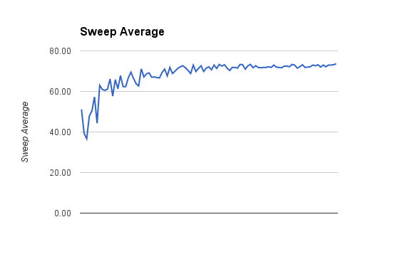
I will set a delay in the FOR loop and see if there is any change.
That will only make matters worse.
I did no know about the sampling limit on the ADC.
So what frequencies are you trying to measure? You would be better off fitting an envelope detector to the input.
I should have included that I was in-fact using solid core from the AD9837 output as an antenna of sorts.
What is the circuit on the input?
Grumpy_Mike:
That will only make matters worse.
Noted. Thank you.
Grumpy_Mike:
So what frequencies are you trying to measure? You would be better off fitting an envelope detector to the input.
I have tried everything from (1Hz, 120Hz) to (1Hz, 970.3kHz). I'll do whatever frequencies you think would most likely show a difference in the input.
I didn't think of using an envelope detector. That certainly seems like less hassle than this. I'll scope one out but continue to try to work this one out in the meantime.
Grumpy_Mike:
What is the circuit on the input?
http://www.instructables.com/file/FR73R4DH2MYISBD/
I had found this one a few months ago and decided to try to implement it. I replaced the inductor with the output of my frequency IC.
Note that you need to know more that the author to spot the inevitable mistakes in an instructables project. Generally they are crap.
I replaced the inductor with the output of my frequency IC.
What? That inductor has two ends your output has one.
I didn't think of using an envelope detector.
But that instructables diagram is basically an envelope detector.
@ Grumpy Mike
Hey don't knock instructables...
I have found some great stuff on there and its way better than pintrest !
You do however have to read all the comments to find out if there were any ERRATA.
@ Eastmanig
It would have been nice to have that link in your first post.
That being said I stick by my Theremin examples to do what you outlined originally.
Hey don't knock instructables...
When you have been around here for long you too will get fed up trying to untangle the mess that site has made in young brains trying to learn.
You do however have to read all the comments to find out if there were any ERRATA.
But they never do.
its way better than pintrest
It wants me to enroll so they can send me spam so I never look at the thing.
@ Grumpy Mike
Yea I see your point...If anyone could take the time to read or search properly we would be almost obsolete.
I get the same problem with emails I send where people only read the first two lines and respond...Its never the answer I was asking for and is a pet peeve of mine often ending with a terse reply to the effect "
did you not read anything I wrote !" but maybe not as polite as that LOL
