Looks kanji to me. The basic geometry may be 32x4 but as implemented in kanji ...
Start feeding it data and see what it does. The timing diagrams are clear enough.
You're on it's tail. Keep after it! LOL.
(Thinking as i type) ... 32x4 with 5x7 char cell. Thats 6x8 with a cell space between chars 6 char cols x 32 chars x 8 char rows ... 6 x 256 x 4 rows = ~6k bits. No, doesn't seem to to fit 6x17 bits. 17 bits. Four nibbles and a spare bit - it IS shown as nibbles and not bytes on the diagram ... See what else you can worry out of that data sheet ... lemme go look again ...
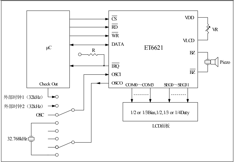
Pinout shows 32 segments (32 = 2^6!) and four COMx lines. Like four, 32 bit characters.
OSCO - Osc Out
OSCI - Osc In
VLCD - LCD Voltage
Vdd/Vss - Vdd/Vss
/CS, /RD, /WR - standard stuff
DATA - I/O so you can read it back out
/IRQ - gotta be an output
BZ/BZ - 2khz/4khz buzzer outputs
Starburst display?
The segment addresses are broken down into two groups. 0-7 and 8-31. Perhaps two different modes?
THIS diagram explains a bit:
The 101 at the front of the WRITE waveform you posted matches the ID column for the WRITE command. So the first three bits aren't synch, but are command group.
The Fx numbers are the frequency dividers for the WDT.
Can you hold the LCD part up to the light and see of you can see the character format? (A polarizer or polaroid sunglasses help) That might explain a lot as to what all these segment lines do. If you walk a 1 thru the segments you can see what order they map to on the display.
I couldn't see anything with the LED off, but with it on and the lens in front of the LCD removed, I see the time in tiny characters in the center. And I'm pretty sure I can see the faint image of the unused segments in the numbers. So I think this LCD can only display four digits and the dots between.
Also, I don't know if it helps, but the connection between the circuit board and the LCD consists of 12 contacts.
Once I think of a way to connect five wires to the connection port thingy, I'll try to send data. The pins are pretty cramped and I can't fit five dupont connectors in there. I could splice into the wires, I suppose.
Ok, I hooked up the wires and ran some code, but couldn't get any segments to activate on the LCD. I just tried a few different data streams. Here's the code for the last one I tried. The data in code variable, formatted to match the timing diagram a little better is 101 000010 0001 0001 0001 1000 1. I'm not sure what to do with the "D" sections.
int latchPin = 5;
int clkPin = 6;
int dataPin = 4;

void setup()
{

  Serial.begin(9600);
  pinMode(latchPin, OUTPUT);
  pinMode(dataPin, OUTPUT);
  pinMode(clkPin, OUTPUT);

  int i;
  unsigned long code = 0b10100001000010001000110001;
  unsigned long chck = 0b10000000000000000000000000;

  digitalWrite(latchPin,LOW);

  for(i = 0; i < 26; i++){
      digitalWrite(clkPin,LOW);

      digitalWrite(dataPin,((chck&(code<<i)) == chck) ? HIGH : LOW);
      Serial.print(((chck&(code<<i)) == chck) ? HIGH : LOW);
      delayMicroseconds(10);

      digitalWrite(clkPin,HIGH);
      delayMicroseconds(10);
  }

  digitalWrite(latchPin,HIGH);

  Serial.println("hey");

}

void loop()
{

}
You might want to try the LCD ON and LCD OFF commands, Those don't need the A parts and are fixed. The X is a padding bit that is ignored but the extra clocks are needed to keep things in sync.
Ok, I think I'm getting somewhere. I wasn't able to get any results from the Write commands you suggested, but I do get something if I enter the LCD ON or LCD OFF commands. Both commands have the same result. It flashes one segment for a moment and you can see the faint image of the rest of the segments. But it only does it if you alternate commands. Doing LCD ON or OFF repeatedly won't have any effect apart from the first time.
Here's a video of the effect, with it alternating LCD ON and LCD OFF every second:
I plan to try the buzzer command while touching a buzzer's terminals to the appropriate pins, although it might be hard because they are so small.
I got it! It took me a lot of sending random commands to see what has an effect, and I found that I needed TURN ON, SYS EN, and XTAL32k to get the LCD working. Also, the command for BIAS 1/3 with 4 COMS to get the segments looking right.
I also searched for English datasheets of similar LCD drivers, and I found one that was almost identical, HT1620. That, and some research on how multiplex LCDs work, got me to realize that there are 32 addresses (the six-bit A number) and four coms (four one-bit numbers).
The timing diagram we were looking at was to update multiple addresses in a row. To just alter one, it's the 101+AAAAAA+DDDD.
Then I just started running through write commands in a loop, incrementing by one, to see what has an effect.
The LCD I have uses addresses 24-31 and all four COMs.
So the top of the first digit is address 24, the bottom of the first digit is 25, top of second is 26, etc.
After the address you want to change, you add the four bits telling it which segments in that address to turn on or off.
For example, to turn on two segments in the bottom of the first digit and turn two off:
101 011001 0110
This was really rewarding and I'm honestly surprised I was able to figure it out. Thanks a lot for your help!
Excellent work! I'm proud of you and you should be proud too. You've reached a milestone in your knowedge and skill set. I know you're better at reading a data sheet no matter what the language!
Well done.
Write it up as a project here when you get it done.
(Just watched the vid. You had to film in the can so you could get it dark enough! LOL)
Great work.
(And you did it without an oscilliscope or a logic analyzer! HARD CORE)
Go over to COMMUNITY/PROJECT HUB and you can do a write up with pictures, code, schematics, whatever you've got. It's certainly a great example of the analytical process that worked.
You've achieved deep hardware & software insights that will serve you will if you continue on this path. You figured out HOW to figure it out!
Paul_KD7HB had a more theoretical approach. You learned a more practical one. Ain'tcha glad you didn't buy an oscilloscope!
Oh cool, yeah I think that'd be fun. First, I'll clean up my code a bit and maybe think of something more interesting for it to do.
My goal with getting into electronics was always cause I wanted to understand how they work, out of curiosity, and so I could customize and/or repair them if needed. So this definitely helped.
Lol, I don't think I would have bought one just for this thing, but if I do ever get one, I'm sure it'd be fun to try doing the same project with some other component but going at it with the oscilloscope.
The technique of analysis was the key. You learned how to SOLVE. Actually when I read your first post my initial reaction was "Good luck", but you provided enough info and effort to make it a learning experience even if all it ever does is Abcd.
How about it showing FIRE and sounding an alarm if there is a hit on an IR Sensor? You you can have it say "Door 3 Open" if there is an issue at night, etc. It's a cool output device. I can think of lots of cute apps. Tie it in with a SD card loaded with a story and have it read you (or your kids) to sleep.
Goose the LED power with a nice fat WHITE light LED (supply power externally) and see if you can't make it ambient room light visible. Use a R/G/B 10mm LED and you can make it change color, Maybe with a BME280 for temp/humidity/baro and have the temp show in color, red if hot, green if ok, blue if cold.
COOL TOY!
BTW: Be sure to post where to buy one, 'cause if you post your build notes, I want one!