Good morning everyone,
I would like to build a program to read the state of a button only at certain times so I was thinking of powering the button for example from pin 3 that I vary HIGH or LOW based on whether I am interested in reading the button and pin 4 that receives current when the button is pressed.
I ask you, can I avoid putting the resistor in series? (Can't you enable the internal resistor like with INPUT_PULLUP?)
And if this was part of the code:
digitalWirte(3, HIGH);
delay(x);
a = digitalRead(4);
What time should I set to be sure enough that it reads correctly ? (button already pressed before digitalWrite...)
If you want to read the state of an input at certain times then write code to do just that and configure the input normally. There is no need to mess around with "powering" the button from another pin
Normally yes, but it would be a bipolar button matrix (4x4 keyboard) that I would like to read without a library but I have already reduced the problem to what I wrote above
No.
INPUT_PULLUP connected a pin to 5V or 3V3 depending on what sort of processor you have, it puts nothing in series.
It looks like we are missing a whole lot of information about these buttons. Are they illuminated? Can you post a link to these buttons?
Can you post a schematic of how you propose to wire them up?
You might want to look at this How to get the best out of this forum before you proceed any further.
We only know what you tell us, and without knowing what you have, we don't stand a chance.
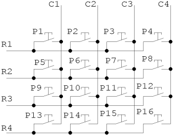
This is the keyboard's circuit diagram, I thought of scanning it like this:
I give power only to R1, I read inputs from C1 to C4, if they are all LOW, I give power only to R2, ...
I was thinking, I should connect C1, C2, C3 and C4 directly to the INPUT pin and with a resistor (and maybe also a diode to prevent the current from another C pin from flowing back to me) to the GND, wouldn't there be a way to connect C1, ... directly to the INPUT pin, without a resistor, without a GND?
To clarify, this called a keyboard ‘matrix’, and unless specifically called out, almost all known keyboards are ‘scanned’ this way - using x-y columns and rows to minimise the number of i/o pins used.
The key values have no relation to the physical layout until they are ‘mapped’ to specific values by the key scanning routines.