Hello Im trying to create an Inverse Kinematic Model for a 3 DOF Robot Arm but the learning curve is kind of kicking my butt here. Ive already got the DH-Parameters and a Forward Kinematic Solver (Which I am not sure is working properly) I also have the DH Parameters set up in Roboanalyzer and they seem to be sound. Id love to talk to somebody with some experience on the topic or just get some tips on how to move on from here towards a useable inverse kinematic model.
Thanks in Advance.
1 Like
I have played with inverse kinematics for my hexapod. Each leg was a 3 servo construct similar to a robot arm like you describe.
I did the math and cooked my own.
What is a DH-Parameter? Forward Kinematic Solver? Roboanalyzer?
1 Like
Did you do it geometrically or how did you solve it?
1 Like
Geometry and trigonometry. (nope. Just geometry. More coffee needed)
We used a function that estimated arctan() because that is an expensive calculation and we used it a lot.
But the angle for the base servo that rotates the entire piece is a simple calculation.
The angle for hip and knee servos are found by finding the intersection of 2 circles and then calculating the angles to that point.
Edit: I had to jump on a call for work. I want to give some examples but that will have to wait for a bit. Darn work. But at least it lets me buy arduinos!
1 Like
Actually, before I jump in with some math, I want to confirm the configuration of your arm.
Do you have a link to the arm? Or a pic?
For my hexapod, 3DOF means 3 servos; base, hip and knee.
The base rotates the entire leg, and the hip and knee control how high and how far out the foot is.
For an arm, the base servo is the same. The shoulder and elbow correspond to the hip and knee for my leg.
But there also can be a wrist, a gripper and a gripper rotator.
All 6 are a 6DOF arm.
Which 3 do you have?
Here is an example of an robotic arm. Note that the gripper rotator is not labeled.

1 Like
Without knowing your arm configuration, let me just talk about calculating the base angle.
Calculating the base servo angle does not require Z, height above the table, at all.
With your arm on a table surface, imaging a 2 axis grid with the arm at the origin.
Assuming that you have a 180 degree servo on the base, you will use 1/2 of the grid.
Lets use the positive Y half. Quadrants I and II from the image below.

I am going to use standard hobby servo degrees, where 90 degrees points directly up the positive Y axis. 0 degrees points left along the negative X axis and 180 points right along the positive X axis.
Look at this grid and the 6 example points on it.

It is easy enough to see that for the sevo arm to point to E, the base servo should be at 90 degrees.
Point to G with zero degrees. And point to A with 180 degrees.
But how to calculate those angles mathematically?
Geometry to the rescue.
Arctan() gives us the results we want.
The servo angle is arctan(y/x) / PI * 180
Clearly we need to handle some edge conditions.
If X = 0 then the angle is 90.
If Y = 0 and X > 0 then the angle is 180.
So walk through the 6 point I pictured and calcualte the angle manually. What do you get?
1 Like
Thank you for the Input. 3 DOF in my case means that I have a base a hip and an elbow so its basically the same as with your leg. Which leads me to believe that it would be possible for me to modify your code for my purpose if youd be willing to send it to me.
If youd like we could discuss this over discord. I find it makes communication far easier.
1 Like
My code is ancient and written in a version of the IDE that was substantially different that is in use today.
It would be much easier to take the concepts and code them than to try to decipher what I did and why.
I even KNOW my own code and looking through it I have to scratch my head and wonder what I was thinking.
Please don't think I am doing this out of a sense of ownership or pride. I honestly believe that your easiest path forward is to use the ideas we are discussing and code them up. There are a lot of people here who appreciate helping others code.
Any chance we could get a pic of your robot arm? Or a link to it online? There are some numbers we need and having an image of the arm would help describe what to do.
Have you successfully uploaded code to your board? Blink and sweep seem like appropriate tutorials if you have not.
I am not against calls, discord or otherwise, but that bypasses one of the big advantages to this forum - history. If we talk outside of this thread, the content will not be usable by future forum members who have questions on similar subjects.
I am not sure I know what your goal is. But if you want an IK function where you pass in the X,Y,Z coordinates and it calculates the 3 servo angles, we can do that. You already have the math for the base servo above. You could start out by creating a function that takes in x,y and z, and returns 3 servo angles where the base servo is calculated using the math discussed, and the shoulder and elbow are just hard coded to be their default parked location (90?).
Then you could feed in a series of XYZ coordinates and push the resulting angles to the servos and see your arm move to point to the selected position.
Make sense?
To be clear, I do not know your level of coding experience. But I AM experienced in helping developers of many different levels.
1 Like
Again thank you so much for your help. I have some coding experience (I made a walking robot and an autonomously driving one with arduino)
If you would give me the formulas for the different angles or the function you were talking about I believe I should be able to convert them into code .
And my ultimate goal is to be able to move the robot end effector in an xyz coordinate space. Because of that the perfect solution of course would be a Function which I would have to supply the three xyz coordinates resulting in it spitting out the three angles needed. The robot is currently only a CAD model as I wanted to have a semi sound solution for coordination before I start machining but I can post a screenshot. The arm wont be driven by servos. I want to use steppers amd lead screws because of the increased accuracy and the non back driveable nature of the joints. But that shouldnt be a problem as I the math needed for converting the linear motion of the screw into joint angles isnt that complicated.

1 Like
Interesting approach.
I am guessing that you will have micro switches for homing the three steppers?
Does the control linkage you have pictured lead to non-linear movement? I suppose that a single stepper step will result in a different angular movement at various points in its travel.
If so, this may make moving the joint to a particular angle challenging.
Is the stepper motor for the base geared also? If the arm is extended, that is a lot of rotational inertial to overcome.
I have seen some arm designs that provide very little in the way of rigid support for the base axis. Some simply screw on the the servo output shaft which then cannot handle the force placed on it when the arm is extended. A bearing at the top and bottom of the main base shaft will provide a strong base axis.
What range or rotation do you expect at each joint?
Yes there will be homing switches.
It may lead to non linear movement but the angle can be figured out with trigonometry. The bearing arrangement for the base consists of a radial ball bearing in combination with an axial ball bearing because of the latter you cann apply some preload which should ensure a rigid setup. The base stepper is not geared but that could maybe change if the steppers power isnt large enough to rotate the arm. The range of motion of the two upper joints is fairly limited (Maybe something along the lines of 60 deg each Id have to look this up in the CAD model)
1 Like
60 degrees.
I think that this will limit the usable volume that the end of the arm will be able to reach.
Not a show stopper.
I have mad a fairly detailed discussion about calculating the base angle. I was going to suggest coding that up so that you can test out the math and your physical device, but it is still in the design stage.
To calculate the angles of the shoulder and elbow, you need to determine the intersecting points of 2 circles.
The shoulder circle has its center at the pivot of the shoulder. The radius of this circle is the length of the segment from the shoulder pivot to the elbow pivot.
The elbow circle has its center at the hand. The radius of this circle is the length of the segment from the elbow pivot to the hand.
Let me knock up a pic and show you what I am trying to get at.
1 Like
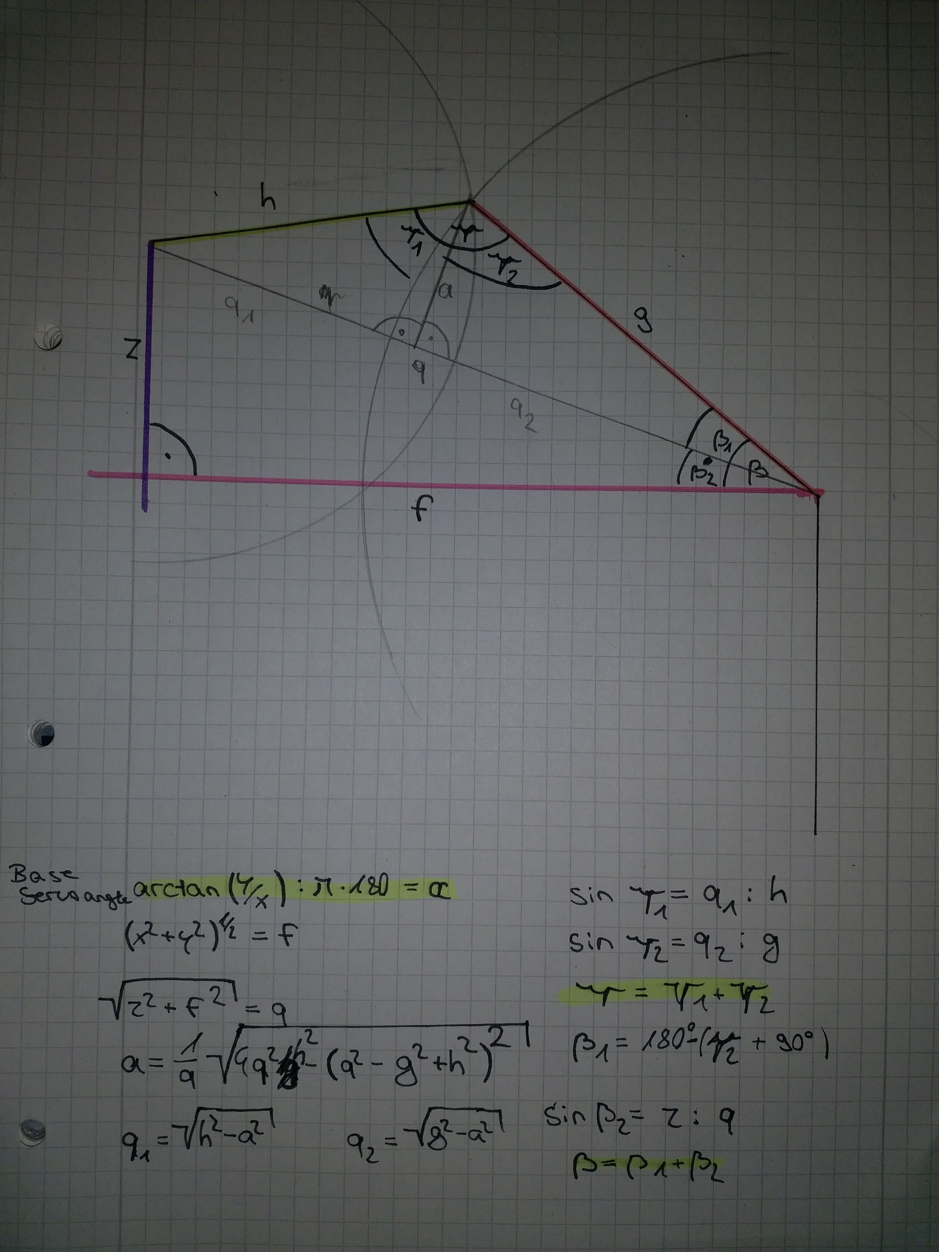
My pic.
The red dot is the pivot point for the shoulder.
The green dot is the tip of the hand.
The blue dot is the pivot point of the elbow.
The length of the pink line segment is (X^2+ Y^2) ^0.5
The length of the purple line segment is Z (depending on the reference, may Z - height of the red point)
The red and green line segments are of the length of your arm pieces. Each is the radius of the respective circles.
Clearly in this case, there are 2 intercept points. We are probably only interested in the higher of the 2 unless your elbow can bend backwards.
From there you are back to some geometry to determine the angle of the red line segment and the angle between the red segment and the green segment.
Those are the angles to set your shoulder and elbow.

1 Like
So, google up how to find the intersection of 2 circles. Stack Overflow is my goto source for things like this.
Let us know if you have problems.
1 Like
Ok im struggling a bit here what would I do with said Intersection point? And in reference to what would it be?
1 Like
Ok nevermind I think I have it figured out. I dont have time to program it right now but the math checks out. Thank you so much for your help. Ill be sure to post a picture of my solution shortly.
1 Like
That's OK. I am throwing around a lot of info. And I may not be describing it well enough.
The circles are on the plane defined by the shaft of the base and the direction of the arm.
The coordinates of the intersection point (blue in the pic above) give us the angle of the shoulder.
Let me drop in a yellow line. Do you see how this lets us define the angle for the shoulder?
Hint, if you know the coordinates of the blue point, you can determine the length of the yellow segment of the opposite side. And you know the length of the red segment since it is the fixed length of your arm piece. That is the Hypotenuse
Sin(angle) = Opposite/Hypotenuse
angle = arcsin(Opposite/Hypotenuse)
Similarly, you can calculate the angle of the elbow. Hint, you will need to take into account the angle of the shoulder since this elbow is attached.
Edit: Oh good! You got it! ![]()
Edit 2: At least I assume so. You have a lot of good looking notes.
The proof will be when you code it up, build it up and program in some points for it to move the hand to. Good luck and post pics!

1 Like
Ok I have a Python script but there always seems to be a mathematical erro. Im guessing this is due to me giving it impossible coordinates. do you have any idea on the range of the points the arm could reach mathematically?
Here is the Python script:
import math
x = float(input("X: "))#
y = float(input("Y: "))
z = float(input("Z: "))
#Link 2 length in mm
g = float(225.375)
#Link 2 length in mm
h = float(195)
#Base joint angle
alpha = math.degrees(math.atan(y/x)) / math.pi * 180
f = float(0)
f = ((x2) + (y2))**0.5
q = float(0)
q = (z2) + (f2)
a = float(0)
a = (1/q) * math.sqrt(4 * (q2) * (h2) - ((q2) - (g2) + (h**2))**2)
q1 = float(0)
q1 = math.sqrt((h2) - (a2))
q2 = float(0)
q2 = math.sqrt((g2) - (a2))
gamma1 = float(0)
gamma1 = math.asin(q1 / h)
gamma2 = float(0)
gamma2 = math.asin(q2 / g)
gamma = float(0)
gamma = gamma1 + gamma2
beta1 = float(0)
beta1 = 180 - (gamma2 + 90)
beta2 = float(0)
beta2 = math.asin(z/q)
beta = float(0)
beta = beta1 + beta2
print("alpha: ",alpha)
print("beta: ",beta)
print("gamma:",gamma)
1 Like
do you have any idea on the range of the points the arm could reach mathematically?
Yes. Ones where the number of circle intercept points is greater than zero.
Which can also be represented as:
The distance from the shoulder pivot to the target point is <= the sum of the lengths of the arm pieces
and
The distance from the shoulder pivot to the target point is >= the difference of the lengths of the arm pieces
That is mathematically. Now realistically, there are other constraints.
The target point must not result in a join angle greater than the mechanical limit of rotation for that joint.
The target point cannot be inside the structure of the arm or base.
The target point cannot be below the surface on which the arm rests (unless you have it setting near the edge of a table)