I am trying to develop an counter using the IR break beam method the distance between the LEDs will be 5mm. Most of the prebuilt devices for arduino have much bigger housings than the space i have available. I can fit some of the 3mm LED's that are part of something like an opto switch but their housings are too big. I can put whatever electronics are needed to control the LEDS on the outside of my box with tha arduino.
Does anyone have any recommendations. I am not knowledgeable enough on what components to get to make this work or even if at such close proximity these type of devices can work
Perhaps think "hall effect switch " such as Alegro 3144....available as an el-cheapo module ky-003 online, cheap as.
Naturally, you don't have to use the complete module, just a pullup resistor (or an LED and resistor to the Vcc line) and a small magnet.
Hi, @mirc66
Have you looked at photo interruptors.
You can cut them down the gap if they need to be separated.
You can also get very small units that may do the job.
thanks everyone... yeah i have looked at photo interruptors this is for an out of the normal insect counter the slot the insectcs go through is 4 mmx7mm and i has to be installed in a location that does not allow a lot of of space. I had tried with photo interruptor opb804 which have the 5mm opening i need but the rest of the housing is much bigger than i can accomodate and it is no longer available. Hence i wanted to see if i could find the combination of 3mm IR emitter and receiver .
Sizing looks great. Pardon the question but i am not very versed on these devices so i find the datasheet a bit confusing. There are various V and I which are the ones i need to make sure match my arduino power of 5V and if i power my arduino with 1Amp power supply and require 4 of these for my application.
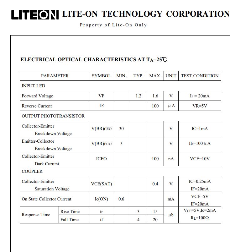
For example the LTH-301-07 datasheet states:
has Vf=1.6V ;Vceo=30V( which would larger than the arduino); Veco=5V, If=20mA
see attached data sheet can someone summarize which of these various voltages and currents i need to match the arduino V and current.
I see what you are saying . But im trying to understand which of the general parameters in the datasheet translate to Vcc as not all companies give such a diagram.
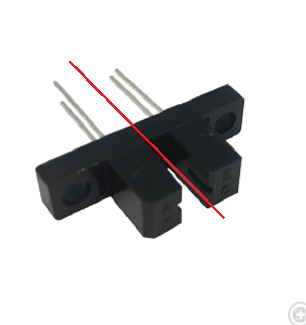
So for a generic opto switch i was trying to figure which parameters i need to ck before i purchase like i have the below item in house . Similar to the liteon it has a V(br)ceo=30V and V(br)eco=5V and If=20mA
so do I allways check the V9br)eco=5v and if the the it will run ok in arduino and if i have If=20 mA would mean i can run 4 on a 1 amp power supply. I am talking in generals what do I look in the datasheet to confirm it would work with arduino