I made a circuit to control an airconditioner.
I used VS1838b.
It works very good in first 5~10 min. But after then, no data signal receives from any remote controller.
So I replace it a new one, 10 minutes works good, and gone again. >:(
Pins are correct, voltage on sensor(VCC) is 4.5V.
I don't know what problem is.
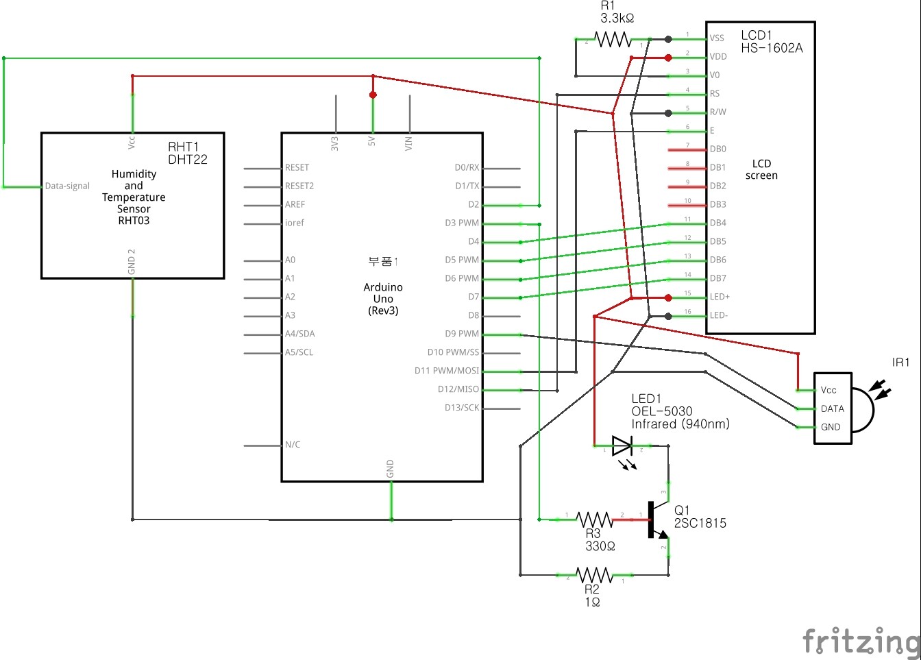
I attached a fritzing img, sorry for unclean diagram.
Should I change the sensor to TSOP than cheap VS1838?
I’m so sorry.
It did not burn. When I reset, works good 10 min again.
It seems problems of code.
Thank you for replies, I’ll confirm this code carefully.
I miss quiet some components from that typical application diagram, this may also be a problem.
There's a 47µF cap across the Vcc and GND pins of the sensor, and a 47Ω resistor in the Vcc line. Those two are probably there to ensure stable power supply to the sensor (and almost certainly needed for stable operation, otherwise there wouldn't be so big a cap indicated).
There's a pull-up resistor indicated - also not in your circuit diagram, and as you didn't post your code I can't see whether you have enabled the internal pullup resistor on that pin. This resistor indicates it's an open collector output, making it mandatory for proper operations.
As it works good for about 10 mins my first suspect is the hardware. Code tends to work or not work, period. Hardware can be more finicky.
Value of R3 is a lowish; value of R2 just can't be right and is on the wrong side of Q1.
Fritzing is indeed notorious for producing horrible circuit diagrams. At least you don't post the breadboard view which is even worse than this. Hand drawn is a good alternative, or if you intend to continue in this hobby take the plunge and learn a proper circuit drawing CAD program such as KiCAD or EagleCAD.