After spending a lot of time working with the Raspberry Pi in its various guises, I got hold of a copy of Getting Started with Arduino.
Working through that, I hit this page.
My local electronics supplier didn't have the IRF520 MOSFET, but they did have the IRF540. Borrowing a 520 from a friend and adding in a 1k resistor to stop the PWM pin floating allowed me to get the circuit to work.
Putting in the IRF540 causes the motor to run away completely. The FET also gets really warm.
My guess is that there's not enough internal resistance in the IRF540 FET (0.27ohm in the 520 versus 0.07ohm in the 540) to keep the motor from running away and it needs a second resistor.
Where would I put that second resistor in? I'm thinking between the Vin line and the source pin on the MOSFET.
Does that sound right?
If so, what value would be good?
That's the thing. With the IRL540, the circuit runs away. The motor rpm quickly reaches maximum and won't return when the PWM signal comes back down.
I just removed the 1k pulldown resistor and the circuit performs the same with the IRF540. The motor runs away.
The FET still gets very hot as well.
The question remaining is why.
Why does the 540 get hot when the 520 doesn't?
Why does the 520 work but the 540 doesn't?
It's going to be interesting finding out.
The plot thickens.
The IRF540 works with much lower light levels, with and without the pulldown resistor. Which means adjusting the constant in the code for PWM.
Is there a setting I need to implement so you can view the Google Books page? It would help if you could see what I was talking about.
The text I'm working from recommends the IRF series.
From what I can read online, the difference is that the IRL series will switch on with much lower voltage levels, suitable for use in logic circuits.
As I'm just tinkering and supply is limited where I am, would the IRF series be fine?
Firstly, thank you for taking the time to help me here. I can see where you're coming from in using the IRL series of MOSFETs, but unfortunately I can't get those easily.
As I've not got the ability to host pictures or sketches, that might be difficult.
It's a pity you can't see the Google Books page.
A Google search for 'Getting Started with Arduino MOSFET' has it as the first link.
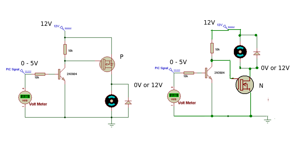
Looking at this link I've got mine wired exactly the same way. The only differences are that I'm using a IRF520 or IRF540 MOSFET and that I've got a 1kohm resistor instead of a 10kohm.
Seeing as both the 520 and 540 are N-channel MOSFETs, it should work the same.
I'm thinking I'll need to alter the resistance of the pull-down resistor to get one MOSFET to work the same as another.
Tashen:
Firstly, thank you for taking the time to help me here. I can see where you're coming from in using the IRL series of MOSFETs, but unfortunately I can't get those easily.
As I've not got the ability to host pictures or sketches, that might be difficult.
It's a pity you can't see the Google Books page.
A Google search for 'Getting Started with Arduino MOSFET' has it as the first link.
Looking at this link I've got mine wired exactly the same way. The only differences are that I'm using a IRF520 or IRF540 MOSFET and that I've got a 1kohm resistor instead of a 10kohm.
Seeing as both the 520 and 540 are N-channel MOSFETs, it should work the same.
I'm thinking I'll need to alter the resistance of the pull-down resistor to get one MOSFET to work the same as another.
The pull down resistor has almost no effect.
It is just there to discharge the gate lead when the arduino powers up
and floats the output pin for some time.
You need to increase the voltage to the gate, using the buffer transistor
shown in the second schematic of the previous post.
Dwight
Thanks everyone for replying to my post and giving me such useful information.
If I'm reading this right, then a 10kohm resistor on either the source or drain pins of the MOSFET should stop the runaway motor. I'll experiment and see what happens. From what I can read about MOSFETs, it shouldn't make too much difference which pin I use.
What would happen if the motor was powered up before the Arduino? Would that cause damage? I've got a diode in place between the drain and source to prevent the flow of current when the motor switches off.
If I understand the diagram right, you're using the 5V PWM signal through the NPN transistor (I've got a BC547 that I can use) to turn on 12V to turn on the MOSFET, thereby allowing 12V to flow through the motor. The diode is across the motor to prevent current flowing back when the motor is switched off and still turning.
I've got a 12V 1.5A external HD power supply with a 2.1mm centre positive barrel connector. I should be able to put that into the Arduino and then take 12V from the Vin pin and use that to run the MOSFET.
Again, thank you everyone for all your help. A small question has given me a whole heap of learning.