Hi, Is someone able to help me please as Im ignorant when it comes to datasheets and the math involved. There is so much information online about fet biasing, its a little overwhelming.
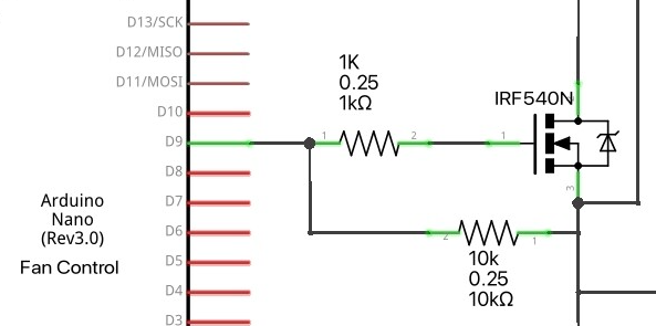
My circuit is a nano running x4 pc fans. Continuous current through an IRF540N is 720mA
My question is for that MOSFET, what value should the gate resistor be? I currently am using 1k. Is this correct and would say 180R keep the FET cooler?
The IRF540 is not logic level so will not fully turn on at 5V on the gate.
The IRL44 is a good logic level N channel MOSFET.
The gate resistor should be on the low side. 180R is good. You want the MOSFET to turn on quickly, but limit gate capacitance charging current. The necessity of the gate resistor has been debated on this forum. I use the gate resistor.
Yeah I know Its not a logic FET. Would it be a simple case of desolder IRF540N and throw in an IRL44? Yeah I kinda thought the 180 would be a go, and yes Ive read many long debates regarding the gate resistor but none of them incorporated the FET Im currently using.
The MOSFET gate is a capacitor, and the purpose of the series gate resistor is to limit the turn-on current draw to a safe value, which is around 20-30 mA for a port pin on an Arduino Nano. 150 Ohms is OK.
But since the IRL540 never turns on completely, it doesn't matter much to use 1K, as you do.
I’ve found it does make a difference with the IRF540. The higher the resistance the harder the gate is to turn on. Eg: x4 pc fans = 720mA. I’m using the map function so initial pwm on is 60 with a 1k on dig pin 9. If I lower the pwm o/p to 40, the fans don’t spin. I’ve changed the the resistor value to 180r and I’m able to start the fans around 30 on dig 9.
You can buy FET modules. You can also find schematics for them if you look hard enough.
The schematic you posted is useless because so many lines go off-page, the context is completely lost.
Consider your goals. If you want to understand electronics, you can not skip over the engineering aspects of it. Those are essential. You can have fun otherwise, but you have to accept canned solutions.