IRremote not Sending 56khz on Arduino Nano

Hello all. I am trying to send an ir signal from one Arduino Nano (ATmega+328P) to another. The project requires that the carrier frequency be 56khz. All the rest of the peripherals are running at 56khz with 56khz receivers. This cannot be changed.

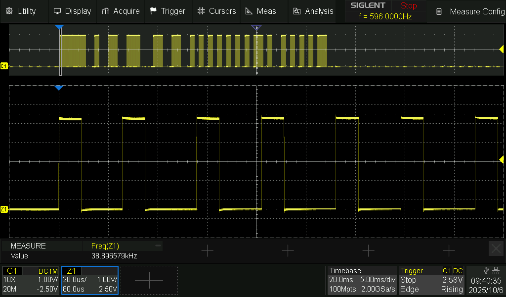
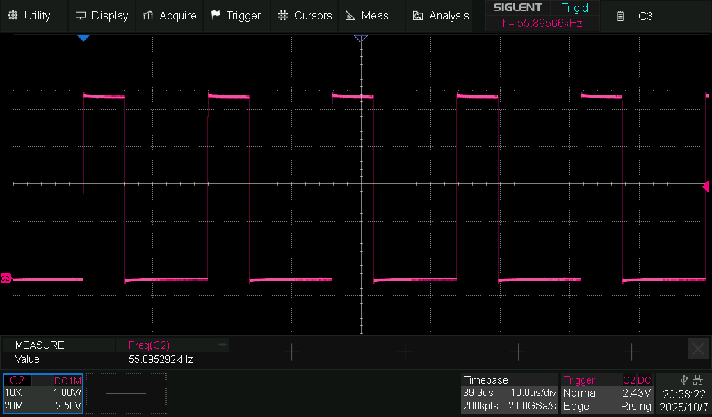
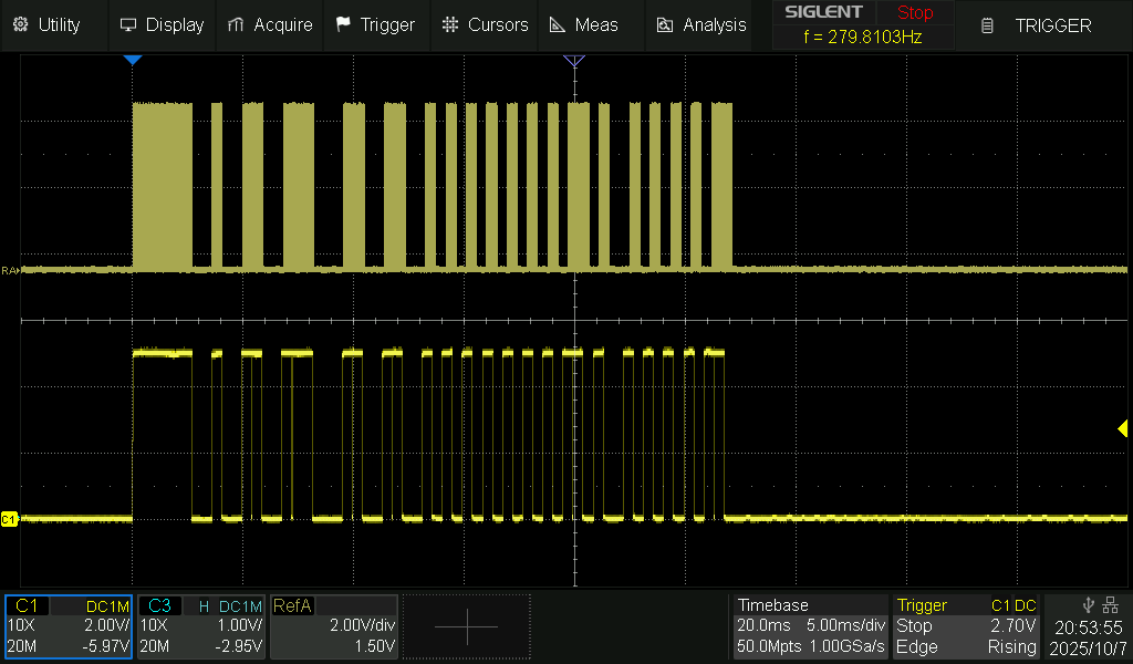
Everything works fine when sending via 38khz for testing. The codes transfer cleanly and can be sent at long distances. Everything works properly at 38khz. But when I change out the receiver and alter the code to using 56khz, the signal sometimes works, but is mostly junk. This tells me that the issue is in sending at 56khz. Yes, I am using 56 kHz receivers (TSOP-4856). In fact, when I change out the code to be 56 kHz but use a 36khz receiver, it still works fine. Which tells me that no matter what I do to the code, it is always sending at 36khz.

The code is simple enough. Any clues as to why I am not getting 56khz output from this? You can see that I am using "irsend.enableIROut(56);" which should force the the change but it isn't.

Any ideas? Thanks in advance.

#include <IRremote.h>

uint8_t nbits = 24;
uint32_t data = 0x5500C1;


const int IR_SEND_PIN = 3;

IRsend irsend;  // Create an IRsend object

void setup() {
  Serial.begin(9600);  // Optional: for debugging
  Serial.println("IR Transmitter Ready");
  irsend.begin(IR_SEND_PIN);
  irsend.enableIROut(56);
}


void loop() {
  irsend.sendRC6(data, nbits);
  Serial.println("RC6 signal sent!");
  delay(2000);
}

Have you read the data sheet for this part?
You can get it from the DigiKey, web site

Two parts to take notice here.

  1. look at and implement the Application Circuit at the top of the Second page. You need that R1 resistor and the C1 capacitor. I know this from my time working in the Set top box industry.

  2. Look at the table just below Fig 14. Are you absoloutly certain that the library you are using follows that procedure to mage the transmission?

Hey there, thank you for the reply. I see the data sheet and what they recommend. One thing to consider, I have been using these receivers, without a resistor and cap, with the rest of the system for several years now with no issue receiving from all of the other 56mhz system that I did not develop. However, now that I am generating and Sending signal to the receiver is when things are falling apart. I do not use a resistor or cap when receiving from the rest of the system and it works fine. I can go down that road, but my troubleshooting doesn't lead me that way. What my troubleshooting is telling me, in my very limited experience, is that the issue is on the sending side, not the receiving side. I may be wrong, but that is what I am coming up with.

Can you clarify what you mean by "mage the transmission?"

What little I can find on the topic is that IRremote uses "irsend.enableIROut(56);" to force the signal to use a 56khz carrier wave and that is what I am using. Yet the signal it is pumping out is not 56khz.

I don't have an Arduino Nano available, but I have tested your code on an Arduino Uno R3 which uses the same ATmega328P.

I can confirm that the code does not produce a 56kHz frequency.

Here is an oscilloscope trace, showing the output from pin 3.
The lower trace is the first part of the upper trace zoomed in (20µs per division).


The frequency measured is 38.9kHz. I've seen it vary between about 33kHz and 39kHz.

To check whether the problem is due to the ATmega328P, I repeated the test on an Uno R4 Minima, a Mega2560 and a Nano ESP32.
All of them gave similar results.

2 Likes

I mean can it follow the procedure in that table. Look at the table and it will tell you things like 10 cycles burst , then after each burst greater than..... maximum number of bursts greater than and so on.

As I said I have worked in the set top box industry and standard practice was to use the device with no R&C for cost reasons. Then a lot of sensors started failing in the field. The company we designed the system for declared a systematic component failure, which involved the reworking (fitting the R&C) to thousands of the set top box in question. This, as you can imagine cost a very lot of money. So while you may get away with it for a long time, it is not the way to do things correctly.

So remember you are the one asking questions, and I am the one giving you practical advice from my 50 years experience working with electronics.

1 Like

You could try this:
Update to IRremote 4.5
Use #define SEND_PWM_BY_TIMER (before #include <IRremote.hpp> line) to enable hardware PWM.
Convert your signal to raw and use sendRaw(rawData, length, 56) .

1 Like

Still coming through at 38khz

17:51:33.848 -> IrSender.sendRaw(rawIRTimings, sizeof(rawIRTimings) / sizeof(rawIRTimings[0]), 38, , );

This suggests to me that library you use to send the code is not setting the frequency of transmission correctly.

What do you mean by "still comming through at 38KHz" It seems to me that you are setting the frequency to 38 KHz and not 56 as suggested by @kmin.

I think the way round this might be to generate the PWM separately at the correct frequency.

You can use one of many websites that walk you through this like Generating PWM

Meandered around this page:

So based on my best guess from what I read around there; in particular this:

Ensure that all macros in your main program are defined before any #include <IRremote.hpp>.
The following macros will definitely be overridden with default values otherwise:
RAW_BUFFER_LENGTH
IR_SEND_PIN
SEND_PWM_BY_TIMER

Therefore that's what I attempted to address in this sketch revision:

#define IRFREQ 56
#include <IRremote.hpp>
uint8_t nbits = 24;
uint32_t data = 0x5500C1;


const int IR_SEND_PIN = 3;

IRsend irsend;  // Create an IRsend object

void setup() {
  Serial.begin(9600);  // Optional: for debugging
  Serial.println("IR Transmitter Ready");
  irsend.begin(IR_SEND_PIN);
  irsend.enableIROut(IRFREQ);
}


void loop() {
  irsend.sendRC6Raw(data, nbits);  // was irsend.sendRC6(data, nbits);
  Serial.println("RC6 signal sent!");
  delay(2000);
}

Hopefully this sketch gives you some joy, or maybe the web link gives you some ideas. I admit that it's a shot in the dark as it is untested, although
it compiled for me ok on Nano board selection, using IRremote library ver 4.4.1 by Shirriff, z3t0 and ArminJo.

The only error your original code threw on ver 4.4.1 was line 22 which I revised to match the compiler suggestion and noted in the comment.

17:51:33.848 -> IrSender.sendRaw(rawIRTimings, sizeof(rawIRTimings) / sizeof(rawIRTimings[0]), 38, , );

Is the response I am getting from the receiver, not the code. This is the code I used and still got 38khz on the receiving end. That last 56 is where I am telling it to use 56khz. But it isn’t.

 irsend.sendRaw(rawData, sizeof(rawData) / sizeof(rawData[0]), 56);

Nor did it send at 56khz when I used the following code as our good friend @JohnLincoln so nicely checked with his oscilloscope. Thank you John, that was genuinely helpful as I don’t have a scope to test the actual output. Thank you.

irsend.enableIROut(56);

Arg! No dice on that one either. Still spitting out 38khz. Thank you for taking a swing at it though.

1 Like

Also tried sending it over Timer 1 on Pin #9 as some have suggested in other forums. No dice there either.

Look at the response here (IrSender.sendRaw), it's syntax from old library vesion.
I suggest you to uninstall all IRremote libraries and then install only 4.5.

Did you try that? What did you get?

A good idea to try.

Dang. Sorry, that's all I got.

I think originally you were using the RC6 protocol. Looking through the IRremote library code, it appears it uses 36KHz for both RC5 and RC6, and I don't see any provision to allow you to change that. But it's a very complicated library, so there may be a workaround that I don't see. But sending raw may be more likely to succeed.

By the way, if you have another Nano or similar, you can detect the transmitted carrier frequency without a scope. You would power the original TXNano from the second RXNano (5V and ground), and connect the output pin of the TXNano to D8 of the RXNano, and connect the RXNano to your computer's USB. The RXNano would run this code to produce output on the Serial Monitor.

// IR_Carrier_Frequency.ino - Uno, Nano, Pro Mini(16MHz) (ATMega328P)
// capture incoming raw IR carrier
// total cycle time - time between falling edges
// 26.32us cycles = 38KHz carrier
// Connect special input circuit to D8

unsigned int total, durations[52];
volatile unsigned int Timer;
volatile unsigned int Capture;
unsigned int prevTimer;
int i, count;
bool endit = false;
float avgCycle;

void setup() {
  pinMode(8,INPUT);
  Serial.begin(57600);
  cli();
  TCCR1A = 0;                                     // set up Timer1
  TCCR1B = 0;
  TCCR1C = 0;
  TCNT1  = 0;                                     // clear Timer1 count
  sei();
}

void loop() {
  cli();
  TIMSK0 = 0;                                     // Disable Timer0 interrupts (millis)
  TIFR1  = 0xFF;                                  // clear flags register
  TCCR1B = 0b00000001;                            // falling edge capture, timer1 on, prescale /1
  TIFR1  = 0xFF;                                  // clear flags
  TIMSK1 = 0b00100000;                            // enable capture interrupt
  TIFR1  = 0xFF;                                  // clear flags
  TCCR1A = 0b00000000;                            // Normal mode, no output, WGM #0
  sei();

  count = 0;
  endit = false;
  Capture = false;

  while (Capture == false);                       // Wait for signal to go LOW
  prevTimer = Timer;

  while ((count < 52) && (endit == false)) {
    durations[count] = Timer - prevTimer;         // vs previous timer count
    count++;
    prevTimer = Timer;
    Capture = false;                              // reset Capture
    while (Capture == false) {                    // Waiting for next Capture
      if ((TCNT1 - prevTimer) > 2000) {           // if too long, stop
        endit = true;
        break;
      }
    }
  }

  TCCR1B &= 0xFE;                                 // stop Timer1 clock
  TIMSK1 = 0b000000000;                           // disable capture interrupt
  TIMSK0 = 1;                                     // resume millis interrupt

  total = 0;
  Serial.println("---");
  Serial.println("Clock cycles at 16MHz:");
  for (i = 2; i < count; i++) {                   // first two cycles can be a bit wonky
    total += durations[i];
    Serial.print(durations[i]);
    Serial.print(" ");
  }
  Serial.print("\nSum of cycle times = ");
  Serial.println(total);
  Serial.print("Number of cycles = ");
  Serial.println (count-2);
  Serial.print("Average cycle time in microseconds = ");
  avgCycle =  ((float)total / ((count-2) * 16));
  Serial.println(avgCycle);
  Serial.print("Frequency in KHz = ");
  Serial.println(1000/avgCycle);  
  delay(1000);                                    // Small pause between readings
}

ISR(TIMER1_CAPT_vect) {                           // Timer1 capture ISR 
  Timer = ICR1;
  Capture = true;
}

If you have an extra IRLED, you can use it to detect the carrier optically from the the TXNano's IRLED output without having to connect the two Nanos. Normally you would use an IR photodiode to detect IR, but an IRLED can also function as a detector, although with much lower effeciency. You would use this circuit:

1 Like

I haven't managed to find the simple and easy solution to the issue.

However I have come up with a work around.

Using 16 bit Timer1 it is possible to generate a continuous 56kHz signal on pin 10.
See gammon.com.au/timers for details.

Code for 56kHz on pin10.
const byte _56kHzPin = 10;

void setup()
{
  pinMode (_56kHzPin, OUTPUT);

  TCCR1A = bit (WGM10) | bit (WGM11) | bit (COM1B1);                  
  TCCR1B = bit (WGM12) | bit (WGM13) | bit (CS10);                    
  OCR1A =  285;                                                       
  OCR1B = 94;                                                         
}

void loop() {
}


It is possible to send an unmodulated signal out of pin 3 by enabling the USE_NO_SEND_PWM macro.
The signal is active low, unless you enable the USE_ACTIVE_HIGH_OUTPUT_FOR_NO_SEND_PWM macro.

These two lines need to be put in the code before #include <IRremote.h>

The upper trace is a saved output of the code from post #1.
The lower trace is the unmodulated output of pin 3

The following code will generate a 56kHz signal on pin 10 and the unmodulated signal on pin3.

#define USE_NO_SEND_PWM
#define USE_ACTIVE_HIGH_OUTPUT_FOR_NO_SEND_PWM
#include <IRremote.h>

uint8_t nbits = 24;
uint32_t data = 0x5500C1;
const int IR_SEND_PIN = 3;
int _56kHzPin = 10;

IRsend irsend;  // Create an IRsend object

void setup() {
  pinMode(_56kHzPin, OUTPUT);
  Serial.begin(9600);  // Optional: for debugging
  Serial.println("IR Transmitter Ready");
  irsend.begin(IR_SEND_PIN);
  
  TCCR1A = bit (WGM10) | bit (WGM11) | bit (COM1B1);
  TCCR1B = bit (WGM12) | bit (WGM13) | bit (CS10);
  OCR1A = 285;
  OCR1B = 94;
}

void loop() {
  irsend.sendRC6(data, nbits);
  Serial.println("RC6 signal sent!");
  delay(2000);
}

You could then drive an IR LED by applying the 56kHz to a pnp transistor(or P channel MOSFET), and applying the pin 3 signal to an npn transistor(or N channel MOSFET).
See schematic below:

I've tested @ShermanP's code from post #17 using the continuous 56kHz output from pin 10.
It works well:

---
Clock cycles at 16MHz:
287 286 287 287 286 287 287 286 287 287 286 287 287 286 287 287 286 287 287 286 287 287 286 287 287 286 287 287 286 287 287 286 287 287 286 287 287 286 287 287 286 287 287 286 287 287 286 287 287 286 
Sum of cycle times = 14333
Number of cycles = 50
Average cycle time in microseconds = 17.92
Frequency in kHz = 55.82
---
Clock cycles at 16MHz:
286 287 287 286 287 287 286 287 287 286 287 287 286 287 287 286 287 287 286 287 287 286 287 287 286 287 287 286 287 287 286 287 287 286 287 287 286 287 287 286 287 287 286 287 287 286 287 287 286 287 
Sum of cycle times = 14333
Number of cycles = 50
Average cycle time in microseconds = 17.92
Frequency in kHz = 55.82
---
2 Likes

It appears that "RC5_RC6_KHZ" is defined in the library's IRProtocol.h file as 36. Perhaps you could change that to 56, reboot the IDE, then compile the original code. Worth a try. Oh, and probably do the Use Timer option.

Raw, it wanted raw. Ok, here is how I got to it. My raw data was wonky so I redid the ReceiveDump example program that came with irRemote and got the clean uint16_t rawData. Then using a very stripped down version of irRemote SendRawDemo I built the code below and told it to send on 56khz, which it actually did. Now it is working. Now I just need to pump up the power on my ir led so it reaches further than two feet. But it works and the code being sent between the Arduinos is super clean. Thank you all for your patience and help.

#include <Arduino.h>
#include "PinDefinitionsAndMore.h" 
#include <IRremote.hpp>

void setup() {
    pinMode(LED_BUILTIN, OUTPUT);

    Serial.begin(5600);

}

const uint16_t rawData[] = {2380,570, 1230,570, 630,570, 580,620, 630,520, 630,570, 630,570, 1230,570, 1180,570, 630,570, 
630,570, 630,570, 580,570, 630,570, 630,570, 630,570, 580,570, 1230,570, 630,570, 1230,570, 580,570, 1230,570, 630,570, 1180,570, 630}; 

void loop() {


    Serial.println("Sent");
    Serial.flush();
    IrSender.sendRaw(rawData, sizeof(rawData) / sizeof(rawData[0]), 56); 

    delay(1000); 

}