Hello to everyone! I would like to ask if this configuration would work to build and assemble an irrigation system for my balcony!
I would mainly like to use an Arduino Uno board, a single relay and a DC Water pump 12 V.
The configuration would be: 12 V DC power supply with wires splitted between water pump and Arduino. Arduino is connected with 5 V, ground and a digital signal to the relay. The relay is connected to the pump with the positive wire coming from the 12 V power supply to the relays in the COM port and going out from ON port to the pump. Finally, pump is connected to negative pole directly with the 12 V power supply. I repeat that the 12 V power supply would power both the pump and the Arduino board.
would that work? Do you have better suggestions? Things I can improve?
No, really across the terminals of the pomp, not in series. So pomp positive to relay, diode cathode to same relay contact, pomp negative to GND (of PSU), diode anode to that same GND. Preferably as close to the motor (connections) as possible.
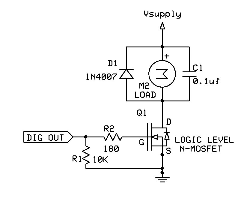
Alternatively use an N-channel MOSFET with a logic-level gate, such as STP16NF06L, instead of the relay. Smaller, more battery efficient, does not click or wear out. Place a 10K resistor from the Arduino pin (connected to the MOSFET gate) to ground, to prevent the pump from running for a few seconds when the Arduino starts up. You still need the diode across the pump terminals.
The only issue I see is the relay powered from the 5V pin of the Arduino, which itself is powered from 12V. That sounds like a good way of getting your on-board regulator to overheat.
Better better... It's non-mechanical so that's in my opinion positive. And you don't need the isolation a relay gives you. "Downside" I don't know of any good mosfet modules so you will have to take out the soldering iron.