While I'm using an Arduino Nano instead of an Arduino Uno, the only difference in my setup is the phototransistor's pin configuration.
Here's what's happening:
Everything worked perfectly initially.
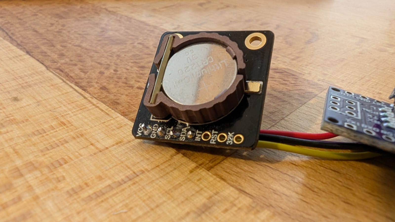
At one point, I tried desoldering the pins and connecting wires directly to the RTC module. I encountered some difficulties desoldering the ground pin due to rapid heat dissipation. It is therefore possible that the DS3231 chip received some more heat than necessary.
After the resoldering, the device was working well for some time tho.
While working on the Code using Arduino IDE I had to flash the device a few times
There was some issue where the Serial connection was not recognized any more, which is why I had to unplug the device from my computer and start over
after some attempts, I was able to flash the device again.
I realized, that something is not working properly since I did not get a steady serial output any more
I added some debug lines, also showing millis() in turn to understand what is happening
It seems as the Arduino is stuck at rtc.begin() for quite some time. And thereafter all calls to the rtc end up in being delayed.
The following picture shows the output
As can be seen, the init takes around 8 seconds. After that every second the log should be sent. But obviously my Nano is waiting quite a long time for something.
Also, we can see that the Date/Time given back has some strange jumps, Even after setting it to the proper moment.
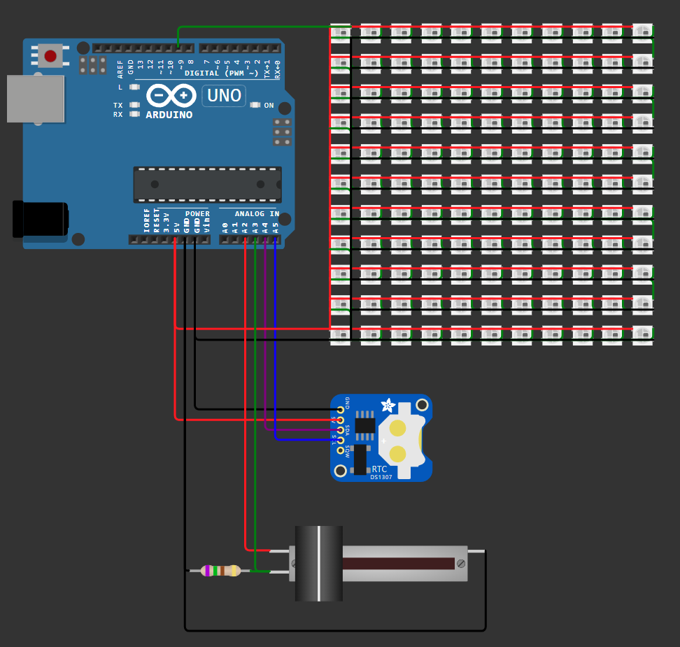
The Leds (121 pieces) and the RTC are powered from the Nano's 5V Pin which in turn is, as far as I understand, directly on the 5V Power rail of the USB connection.
Since a maximum of 24 Pins are active at the same time and mostly driven with a small current, the USB PSU should handle it well enough.
Also, I'm confused to see that it works properly sometimes. But not reliably.
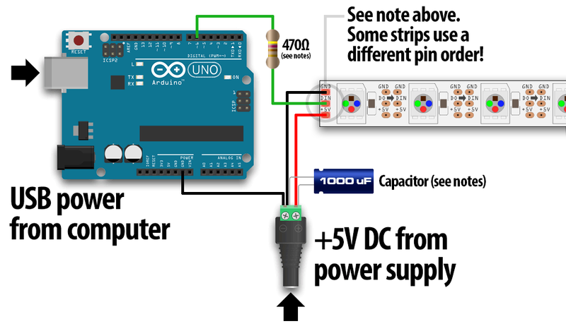
I read about the resistor that should be used to protect the data pin of the Arduino sending signals to the NeoPixel Leds (Which I don't have in place) but I also don't see where back EMF on the data pin should have an impact on the rtc.
Until now, I fried two RTC Modules this way. And I would like to understand what is cauing the issue
I have the same Setup running 3 Times and almost the same setup using an Arduino Pro Mini. These four clocks are working properly.
Thank you for the fast feedback: Usually when one asks for an insight on a part of the code, first responders rant about not having all they need to understand
For all who want to see the whole picture - the wokiwi shows that.
The scaled down information is now here
Schematics:
Disconnecting The Leds and / or the phototransistor does not change the behaviour.
Flashing an DS3231 example sketch shows the same behaviour still. So the RTC is gone from what I see.
I would like to understand if disconnecting the Leds. Or de-powering the whole system could damage the RTC via back EMF.
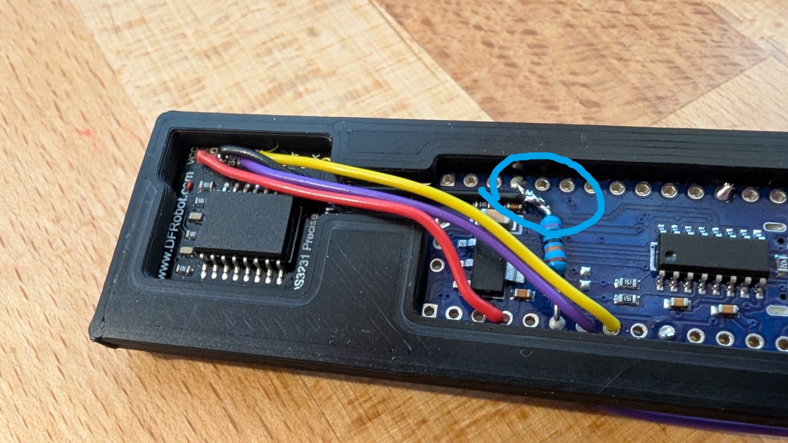
Sorry, I don’t follow links. Please post your annotated schematic here, clearly showing exactly how you have wired the setup. Be sure to include all connections, hardware components, power sources, and any other relevant details. Since soldering damage is a possibility, please also share some clear, close-up pictures of the affected area. Ensure the images are detailed enough to allow for proper evaluation.
Added after it was closed: Your soldering is close, just leave your iron on the joint a bit longer until the solder flows like water. Overall it looks good and thanks for letting us know you found the problem.
Thank you for asking for some detailed Pictures. Clipping the Nano and the RCT out of the bracket revealed that the ground connection of the RTC (to the leg of the resistor) was a cold solder joint!